


7
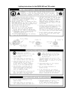
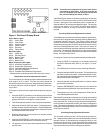
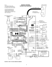
Figure 2. WHC 1502 Ignition Control Board
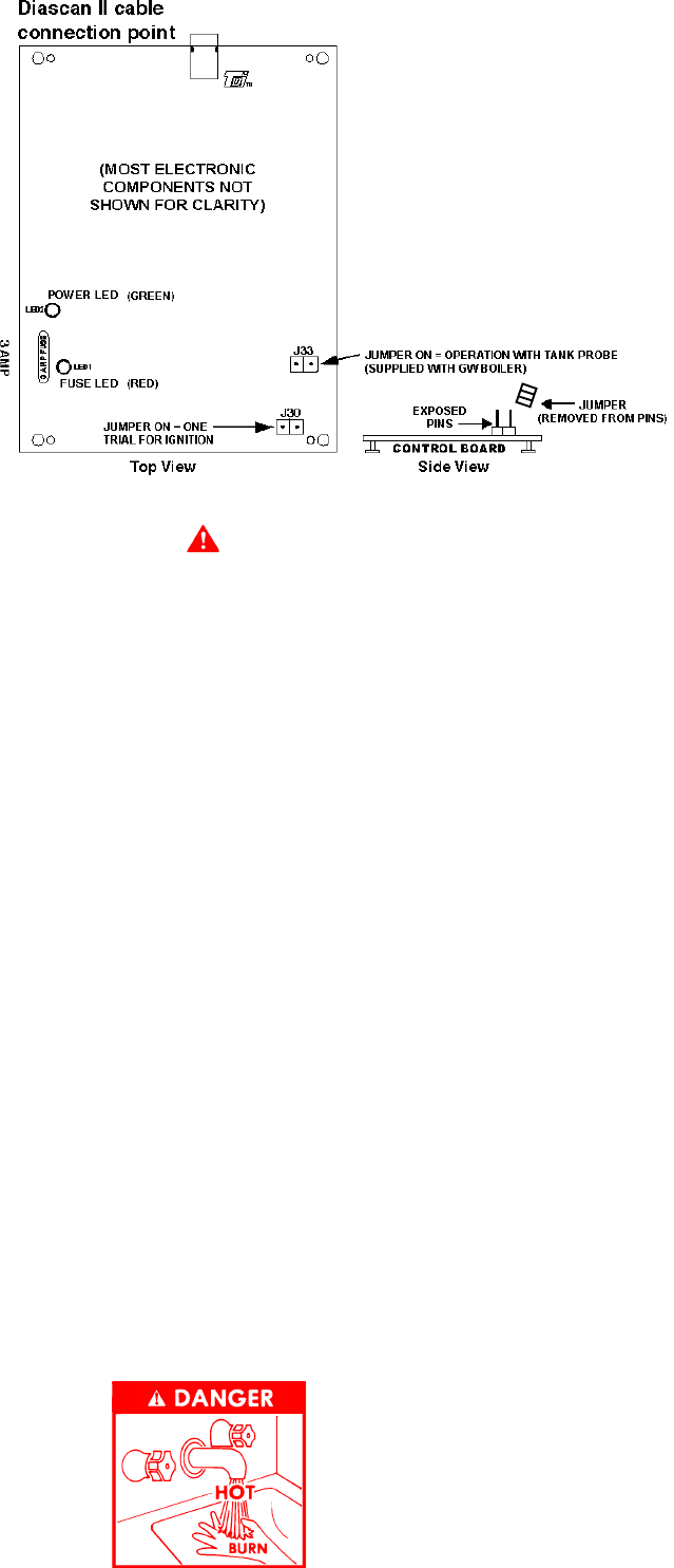
DANGER
HOT WATER TEMPERATURES REQUIRED FOR AUTOMATIC
DISHWASHER AND LAUNDRY USE CAN CAUSE SCALD
BURNS RESULTING IN SERIOUS PERSONAL INJURY AND/
OR DEATH. THE TEMPERATURE AT WHICH INJURY OCCURS
VARIES WITH THE PERSON'S AGE AND TIME OF EXPOSURE.
THE SLOWER RESPONSE TIME OF DISABLED PERSONS
INCREASES THE HAZARDS TO THEM. NEVER ALLOW SMALL
CHILDREN TO USE A HOT WATER TAP, OR TO DRAW THEIR
OWN BATH WATER. NEVER LEAVE A CHILD OR DISABLED
PERSON UNATTENDED IN A BATHTUB OR SHOWER.
THE WATER HEATER SHOULD BE LOCATED IN AN AREA
WHERE THE GENERAL PUBLIC DOES NOT HAVE ACCESS TO
SET TEMPERATURES.
It is recommended that lower water temperatures be used to
avoid the risk of scalding. It is further recommended, in all cases,
that the water temperature be set for the lowest temperature
which satisfies the user's hot water needs. This will also provide
the most energy efficient operation of the water heater and
minimize scale formation.
SETTING THE WATER HEATER TEMPERATURE AT 120°F WILL
REDUCE THE RISK OF SCALDS. Some states require settings
at specific lower temperatures. Table 1 below shows the
approximate time-to-burn relationship for normal adult skin.
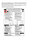
Table 1: Risk of Scalds
Temperature Time to Produce 2nd & 3rd
Setting Degree Burns on Adult Skin
Over 170°F Nearly instantaneous
160°F About 1/2 second
150°F About 1-1/2 seconds
140°F Less than 5 seconds
130°F About 30 seconds
120°F or less More than 5 minutes
Display Board LED Indicators
The Display Board contains eleven (11) solid state LED indicators
for viewing various states of appliance operation and for trouble-
shooting if problems occur. Under normal operating conditions, the
appropriate LED’s will sequence with steady illumination according
to the particular appliance operating state. In cases where prob-
lems or a lockout occurs, the appropriate LED’s will illuminate indi-
cating the general area where the problem exists.
A description of the LED’s and their corresponding functions are
as follows.
LED Controller Function
Call for Heat Monitors Outlet water temperature minus
Switching Differential and thermostat circuit or
tank probe circuit. LED is ON when the tem-
perature at Outlet Water Probe is less than the
set-point minus the switching differential, and the
thermostat circuit or tank probe circuit is closed.
Flow Switch Monitors the condition of the flow switch. LED
is ON when the flow switch closes, indicating
water flow through the system.
Pressure Switch Monitors the condition of the pressure switch(s).
LED is ON when the pressure switch(s) are in
their correct state.
Ignitor Current Monitors current flow through the ignitor element.
LED is ON when current flow through the ignitor
is sensed.
Gas Valve Monitors Gas Valve output. LED is ON when
the output relays supplying power to the gas
valve(s) is closed.
Flame Sense Monitors the Flame Sense Rod. LED is ON
when a signal from the flame rod is sufficient to
indicate flame.
Blocked Inlet Indicates a blockage or interference at the ap-
pliance air inlet.
Blocked Flue Indicates a blockage or interference at the ap-
pliance flue.
Blower Fail Indicates an error/malfunction in the blower
motor circuit.
Circulate Fail Indicates an error/malfunction in the circulating
pump circuit.
Ignition Fail Indicates a malfunction in the ignition system
circuit.
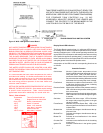
TANK PROBE JUMPER J33 IS ON AS DEFAULT, READY FOR
USE WITH TANK PROBE SUPPLIED WITH THE BOILER (GW
MODELS ONLY. SEE FIGURE 3 FOR CONNECTION DIAGRAM).
FOR STANDARD TANK CONTROLS (e.g., 24 VAC
HONEYWELL AQUASTAT) REMOVE THIS JUMPER AND
CONNECT THE CONTROL TO THE BROWN WIRES IN THE
JUNCTION BOX ON THE BACK OF THE BOILER.
TROUBLESHOOTING IGNITION SYSTEM