


5
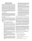
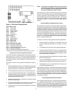
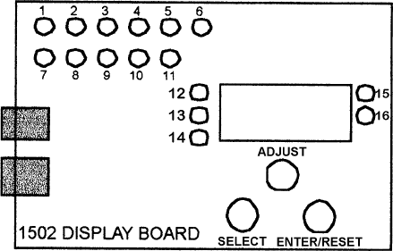
Figure 1. Dia-Scan II Display Board.
Green Status Lights
LED 1: Call for Heat
LED 2: Flow Switch
LED 3: Pressure Switch
LED 4: Ignitor Current
LED 5: Gas Valve
LED 6: Flame Sense
Red Fault Lights
LED 7: Ignition Fail
LED 8: Circulate Failure
LED 9: Blower Failure
LED 10: Blocked Inlet
LED 11: Blocked Flue
Water Temperature Set Lights
LED 12: Inlet Water Temperature *
LED 13: Outlet Water Temperature
LED 14: Inlet/Outlet Differential Temperature
LED 15: Set-Point Temperature
LED 16: Outlet/Set-Point Differential Temperature
* Defaults to tank probe temperature when tank probe is used.
Temperature Set-point Adjustment Procedure
The control board has a standard programmable temperature set-
point range of 110°F to 240°F. The user can easily change the
temperature set-point at any time by using the following procedure.
In all cases, the boiler must be energized. The factory default set-
ting is 180°F.
To change or view the current programmed temperature set-point
value:
1. Press the SELECT push-button on the display board until both
the Set-Pt LED (LED 15, see figure 1) and Outlet Water Tem-
perature LED (LED 13, see figure 1) are illuminated.
2. The LED display will show the current set-point temperature.
3. Press and hold the ADJUST push-button. The displayed tem-
perature will either increase or decrease. To alternate between
increasing or decreasing the temperature, release then press
and hold the ADJUST push-button.
4. When the desired set-point temperature is reached, release
the ADJUST push-button.
5. Press the ENTER/RESET push-button once, this enters the
selected set-point temperature into controller memory.
6. The appliance will now control the temperature to the desired
set-point value.
NOTE: The boiler must complete a full cycle in order for the
new setting to take effect. If the unit is turned off
prior to a complete cycle the setting will be lost and
the previous setting will remain in effect.
If the ADJUST push-button is held down long enough, the set-point
will reach 110°F, the minimum value (or 240°F, the maximum value)
and stop. At this point, if the desired set-point is not obtained, re-
lease the ADJUST push-button and depress it again. The set-point
value will now restart at 110°F (240°F) and once again increase
(decrease) in value for as long as the ADJUST push-button is
pressed.
Switching Differential Adjustment Procedure
To facilitate proper operation and maximize appliance performance,
the control has a programmable operating switching differential or
"hysteresis" about the set point. This means a call for heat will
become active when the water temperature measured at the outlet
temperature sensing probe (Probe #1) drops to the set-point value
minus the switching differential value. The burner will remain on
until the water temperature measured at probe #1 reaches the set-
point value. The switching differential value is fully programmable
from 5°F to 50°F using the push-button(s) located on the Display
Board. The default is set at 20°F.
To change or view the current programmed switching differential:
1. Press the SELECT push-button on the display board until
the Set-Pt differential LED (LED 16, see figure 1) is illumi-
nated.
2. The LED display will show the current switching differential.
3. Press and hold the ADJUST push-button. The displayed value
will either increase or decrease. To alternate between increas-
ing or decreasing the switching differential, release then press
and hold the ADJUST push-button.
4. When the desired switching differential is reached, release
the ADJUST push-button.
5. Press the ENTER/RESET push-button once, this enters the
selected switching differential value into controller memory.
6. The appliance will now control temperature utilizing the de-
sired switching differential value.
If the ADJUST push-button is held down long enough, the switching
differential setting will reach 5, the minimum value (or 50, the maxi-
mum value) and stop. At this point, if the desired switching differen-
tial is not obtained, release the ADJUST push-button and depress it
again. The switching differential value will now restart at 5 (50) and
once again increase (decrease) in value for as long as the ADJUST
push-button is pressed.
Circulating Pump Adjustment Procedure
The Controller is factory set with a 45 second post
circulate func-
tion. Using the Display Board, the user has the capability to choose
between a 45, 90, or 180 second post circulate time period, or turn
the pump on continuously. This provides flexibility in selecting the
post circulate time to meet specific application requirements, and
improves the efficiency of the circulating pump operation.