


4
ELECTRONIC HOT SURFACE
IGNITION CONTROL BOARD
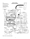
ALL MODELS - The WHC1502 ignition control board is a fully
integrated, state of the art electronic control system. The ignition
control board includes a microprocessor, which governs all
temperature and ignition control functions for the appliance. Inherent
in the design are the normal operating sequences and safety features
associated with a gas ignition control system. The ignition control
continuously performs various diagnostic tests to verify proper
appliance and control operation. Should an unsafe condition occur,
the control will shut down the burner and illuminate the appropriate
diagnostic indicators on the Display Board, indicating a need for
service. All operating programs are stored in permanent memory
on the ignition control and a second programmable memory is used
for retaining user-specific operating parameters in the event main
power is ever interrupted.
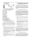
Line Polarity Indicator
A green LED is mounted on the ignition control to indicate line volt-
age polarity is properly connected. When 120 VAC input power is
properly connected to the Ignition Control Board, the green LED will
illuminate. If an error is made when connecting 120 VAC input
power, this LED will not light. Improperly connecting the input power
may result in a false flame sensor failure.
Fuse Protection
The 24 VAC circuitry is protected with a 3 amp auto fuse. If the fuse
opens, a red LED located near the fuse will light. If the red LED is
illuminated, replace the fuse (recommended replacement part is
Little fuse p/n 257003 automotive fuse). Repeated failure of the
fuse is an indication of possible damage to the ignition con-
trol board.
NOTE: One extra fuse is supplied with the boiler.
Typical Control/Appliance Operating Sequence
1. When power is applied to the WHC1502 ignition control,
the Display board will initially run through a self-diagnostic
routine, and then go into its operating mode, displaying
the temperature sensed at temperature probe #1 (Out-
let).
2. If the ignition control board determines the actual outlet
water temperature at the temperature sensing probe
(probe #1) is below the programmed temperature set-point
less the switching differential, and the thermostat circuit
or tank probe circuit closes, call for heat is activated.
3. The ignition control board then performs selected system
diagnostic checks. This includes confirming the proper
state of the ECO/High Limit device, flow switch, and pres-
sure switches.
4. If all checks are successfully passed, the circulating pump
circuit is energized, then the combustion blower is ener-
gized for the 20 second pre-purge cycle.
5. When the pre-purge cycle is complete, the ignitor is ener-
gized. The pump and blower should continue to run.
6. The ignition control board will verify ignitor current. After
the verification, the gas valve will open, allowing gas to
enter the burner.
7. After an additional 1 second, the ignition control board will
monitor the flame sense probe to confirm a flame is
present. If a flame is not verified within 4 seconds, the gas
valve is immediately closed, and the ignition control board
will return to step 2, unless jumper J30 is in place (ON),
see figure 2.
8. If a flame is confirmed, the control will enter the heating
mode where it will continue heating until the set-point tem-
perature is reached, and the thermostat circuit opens. At
that point, the gas valve is closed and the control enters
the post-purge and post-circulating cycles.
9. The combustion blower will run for a 25 second post purge
cycle. When the post purge cycle is complete, the blower
is de-energized and will coast to a stop. The circulating
pump will continue with the post-circulate cycle for the
selected amount of time, factory default is 45 seconds.
See circulating pump adjustment procedure on page 5
and 6 of this manual.
10. The control now enters the idle state while continuing to
monitor temperature and the state of other system de-
vices. If the outlet temperature drops below the set-point
value minus the switching differential, and the thermostat
circuit or tank probe circuit closes, the control will auto-
matically return to step 2 and repeat the entire operating
cycle. During this idle state, if the control detects an im-
proper operating state for external devices such as the
ECO switch, air pressure switch, gas pressure switch,
etc., the appropriate LED(s) on the Display Board will illu-
minate indicating the nature of the fault.
DIA-SCAN II DISPLAY BOARD OPERATING PROCEDURES
The Display Board provides a user-friendly interface to the
WHC1502 Ignition Control Board. With the Display Board, the
user can control appliance functions and view the overall oper-
ating status of the appliance. If an error condition occurs, the
Display Board will scroll a message across the LED display,
indicating the error code. Under normal operating conditions,
the four digit LED display on the Display Board will continuously
illustrate the water temperature sensed at temperature probe
#1 (Outlet). The push buttons on the Display Board allow the
user to program and view the desired water temperature set
point. The Display Board is connected to the Ignition Control
Board through a 6 conductor cable assembly with modular plug
terminations. In addition, an 8 conductor modular jack on the
Display Board allows for connecting a remote display board.
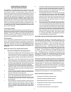
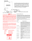
When power is applied to the WHC1502 System, the Display Board
will initially run through a self-diagnostic test, and then display the
Outlet temperature. To display a specific setting or temperature,
press the SELECT push-button until the appropriate LED is illumi-
nated (see figure 1). After 5 seconds, the Display Board will auto-
matically revert to displaying the Outlet temperature. Pressing the
ENTER/RESET push-button will hold the display in the indicated
mode until the SELECT push-button is pressed.
With the Display Board, the user can make adjustments to many of
the appliance’s control features. This includes the following:
Options/Features Setting Procedures
• Set Appliance Temperature Set-point Value
• Set Appliance Switching Differential Value
• Select Appliance Post-Circulate Time
• Set Appliance Circulating Pump to Continuous ON Mode
• Check Appliance Cycle Count
• Control the water temperature in a storage tank