


6
To change or view the current programmed post-circulating time:
1. Press the SELECT push-button on the display board until the
LED display reads OPt (Options).
2. To enter into the options mode, press the ENTER/RESET push-
button.
3. The display will illustrate Circ. Enter this mode by pressing the
ENTER/RESET push-button.
4. The display will now illustrate the current post circulate time.
Press the ADJUST push-button to select the desired post cir-
culate time (45, 90, 180, On).
5. When you have selected the desired post circulate time mode,
press the ENTER/RESET push-button once, this enters the
selected post circulate time into controller memory.
6. The display will automatically resort to illustrating the outlet tem-
perature.
Display Current Mode
In this mode, the Display Board will illustrate the current functional
step in the appliance operational sequence. For example, if the
appliance is performing Ignitor Warm-up, the display will illustrate
IGnt. To enter into this mode, perform the following steps:
1. Press the SELECT push-button on the display board until the
LED display reads OPt (Options).
2. To enter into the options mode, press the ENTER/RESET push-
button.
3. The display will illustrate Circ. Press the SELECT push-but-
ton until the display illustrates StEP. Enter this mode by press-
ing the ENTER/RESET push-button.
4. The display will illustrate the current appliance operating step.
5. The display will automatically resort to illustrating the outlet tem-
perature. To keep the display in the Display Step Mode, press
ENTER/RESET twice in step 3.
Display Message Appliance Mode
IdLe Idle state
NoSn Wait for No Sensor Inputs
CrSn Wait for Circulate Sense
Circ Circulate Pump is ON
PrSn Wait for Blower Pressure
Sense
PreP Pre-Purge state
IGnt Ignitor Warm-up
rEdn Turn ON redundant Gas
Valve relay
IAct Turn ON Gas Valves
StAb Turn OFF Ignitor and wait for
Flame Sense Stabilization
HEAt Heat Mode
PoPC Post Purge and Post Circu-
late
Po C Post Circulate
Display Total Cycle Count
The Main Control Board counts the number of cycles the appliance
has operated. In the Main Control Board, a cycle is counted every
time the gas valve is energized. To access this number, perform
the following procedure:
1. Press the SELECT push-button on the display board until the
LED display reads OPt (Options).
2. To enter into the options mode, press the ENTER/RESET push-
button.
3. The display will illustrate Circ. Press the SELECT push-but-
ton until the display illustrates Count. Enter this mode by press-
ing the ENTER/RESET push-button.
4. The display will now illustrate the current number of cycles the
appliance has cycled through.
5. The display will automatically resort to illustrating the outlet tem-
perature.
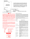
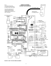
TANK PROBE INSTALLATION PROCEDURE
A tank probe is supplied with each hot water supply boiler. When
installed on a tank, the inlet water temperature on the Dia-Scan II
will default to the tank temperature. See figures 2 and 3 to add
the tank jumper to the control board so that the tank probe is
active.
A tank probe is NOT supplied with the hydronic heating boilers
(GB's). Therefore, a loop or operating thermostat must be provided.
This field-supplied operating thermostat should be wired to the
BROWN wires at the junction box. The jumper at location J33 on
the control board must NOT be on. Refer to figures 2 and 3 for the
location of this jumper.
Tank Probe Set-Point Adjustment
When tank probe is installed in a storage water tank, and the tank
probe is used with the WHC1502 system, the controller will monitor
and control the temperature of the water at the tank probe location.
Setting the tank probe set-point temperature is accomplished
through the Display Board control panel. The standard program-
mable temperature range for the indirect water tank is 110°F to
190°F. The switching differential of the probe is fixed at 5°F.
Tank Probe Temperature Set-point Adjustment Procedure
The user can easily change the tank probe water temperature set-
point at any time by using the following procedure:
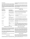
1. Press the SELECT push-button on the display board until
both the Set-Pt LED (LED 15, see figure 1) and Inlet Wa-
ter Temperature LED (LED 12, see figure 1) are illumi-
nated.
NOTE 3: When a tank probe is connected to the board
at location CN10, the Inlet Water Temperature
LED defaults to Tank Water Temperature.
2. The LED display will show the current tank set-point tem-
perature.
3. Press and hold the ADJUST push-button. The displayed
temperature will either increase or decrease. To alternate
between increasing or decreasing the temperature, re-
lease then press and hold the ADJUST push-button.
4. When the desired set-point temperature is reached, re-
lease the ADJUST push-button.
5. Press the ENTER/RESET push-button once, this enters
the selected tank set-point temperature into controller
memory.
6. The appliance will now control the tank water temperature
to the desired set-point value.
If the ADJUST push-button is held down long enough, the set-point
will reach 110°F, the minimum value (or 190°F, the maximum value)
and stop. At this point, if the desired set-point is not obtained, re-
lease the ADJUST push-button and depress it again. The set-point
value will now restart at 110°F (190°F) and once again increase
(decrease) in value for as long as the ADJUST push-button is
pressed.