


8
NOTE: This unit can be vented using only PVC (Class 160,
ASTM D-2241; Schedule 40, ASTM D-1785; or Cellular Core
Schedule 40 DWV, ASTM F-891), Schedule 40 CPVC/ASTM
F-441), or ABS/ASTM D-2661) pipe. The fittings, other than
the TERMINATION TEE should be equivalent to PVC-DWV
fittings meeting ASTM D-2665 (Use CPVC fittings, ASTM F-
438 for CPVC pipe and ABS fittings, ASTM D-2661/3311 for
ABS pipe. If CPVC or ABS pipe and fittings are used, then the
proper cement must be used for all joints, including joining
the pipe to the Termination Tee (PVC Material). If local codes
do not allow the use of the PVC termination when a material
other than PVC is used for venting, than an equivalent fitting
of that material may be substituted if the screens in the PVC
terminal are removed and inserted into the new fitting.
PVC Materials should use ASTM D-2564 Grade Cement;
CPVC Materials should use ASTM F-493 Grade Cement and
ABS Materials should use ASTM D-2235 Grade Cement.
NOTE: A. For water heaters in locations with high ambient
temperatures (above 100°F) and/or insufficient dilution air, it
is recommended that CPVC or ABS pipe and fittings be used.
B. The SUPPLIED VENT TERMINAL must be used in all cases.
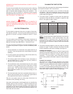
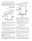
4. The temperature of the flue gases leaving the blower is about
160°F after mixing the dilution air in the inlet adapter of the
blower. Even with high concentrate of room air taken into the
vent system for dilution air, there will be some installations
where condensate will be formed in the horizontal runs of the
vent system. This condensate will run into the condensate
boot attached to the blower and out the fitting. The water
heater is shipped with condensate hose that attaches to the
fitting on the condensate boot. No other Tee or fitting is
required. See Figures 8 and 9.
INSTALLATION OF VENT SYSTEM
Before beginning installation of piping system thoroughly read
the section of this manual VENT PIPE PREPARATION.
If you are installing your system so that it vents through roof,
please refer to following section titled INSTALLATION OF
VERTICAL VENT SYSTEM.
VENT TERMINAL INSTALLATION, SIDEWALL
1. Install the vent terminal by using the cover plate as a template
to mark the hole for the vent pipe to pass through the wall.
BEWARE OF CONCEALED WIRING AND PIPING INSIDE THE
WALL.
2. If the Vent Terminal is being installed on the outside of a
finished wall, it may be easier to mark both the inside and
outside wall. Align the holes by drilling a hole through the
center of the template from the inside through to the outside.
The template can now be positioned on the outside wall using
the drilled hole as a centering point for the template.
3. A) MASONRY SIDE WALLS
Chisel an opening approximately one half inch larger than
the marked circle.
B) WOODEN SIDE WALLS
Drill a pilot hole approximately one quarter inch outside of
the marked circle. This pilot hole is used as a starting point
for a saws-all or sabre saw blade. Cut around the marked
circle staying approximately one quarter inch outside of the
line. (This will allow the vent to easily slide through the
opening. The resulting gap will be covered up by the Vent
Terminal cover plate.) Repeat this step on inside wall if
necessary.
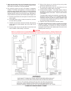
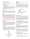
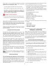
SEQUENCE OF INSTALLATIONS, FIGURE 5
Cut a length of 3" PVC pipe about 3.5 inches longer than the wall
thickness at the opening. Glue the vent terminal "TEE" with
screens to this section of pipe. Slide the wall plate over the pipe
to stop against "TEE". Place a bead of caulking (not supplied)
around the gap between the pipe and cover plate. Apply enough
to fill some of the gap between the pipe and wall. Place some of
the caulking on the back of the plate to hold it against the wall
after installation. If the vent pipe is installed up to the wall, with
a coupling on the end against the wall opening, the pipe with the
vent terminal can be prepared for gluing before inserting through
the wall. Slide the pipe through the wall and insert into the
coupling on the other side of the wall, making sure that the vent
terminal ends up pointed in the correct position. (See fig. 5).
VENT TERMINATION - FIGURE 5
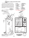
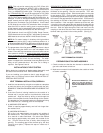
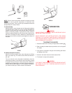
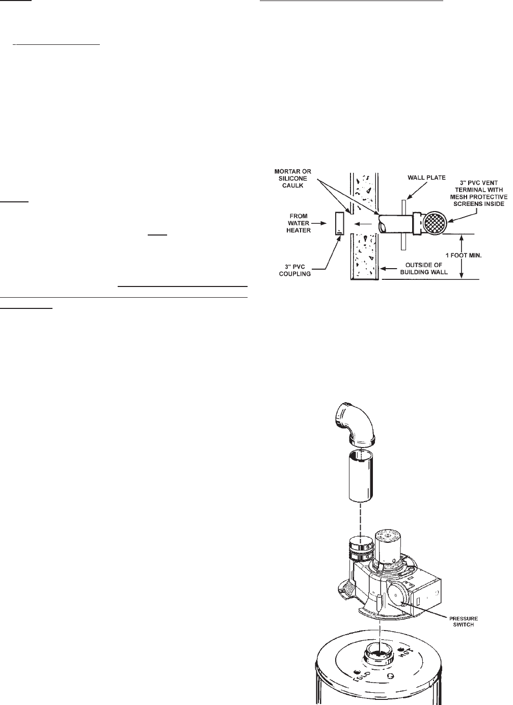
PREPARATION OF BLOWER ASSEMBLY
1. Check to make sure that the wire harness is attached to the
gas valve and blower control box.
2. Make sure no material is still attached to the outside or inside
of blower assembly.
FIGURE 6
MUST INSTALL MINIMUM OF 2" LONG
PIECE OF 3" PIPE INTO ELBOW TO
MOUNT ON BLOWER DISCHARGE
ADAPTER. MAXIMUM LENGTH FOUR
(4) FEET.