


6
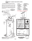
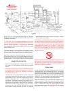
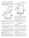
REFER TO FIG. 1 FOR CONNECTION DETAILS. BEFORE
ATTACHING THE GAS LINE BE SURE THAT ALL GAS PIPE IS
CLEAN ON THE INSIDE.
TO TRAP ANY DIRT OR FOREIGN MATERIAL IN THE GAS
SUPPLY LINE, A DIRT LEG (SOMETIMES CALLED DRIP LEG)
MUST BE INCORPORATED IN THE PIPING, FIG. 1. The dirt leg
must be readily accessible. Install in accordance with
recommendations of serving gas supplier. Refer to the latest
edition of ANSI Z223.1.
To prevent damage, care must be taken not to apply too much
torque when attaching gas supply pipe to thermostat gas inlet.
The thermostat inlet has a pad for use with a backup wrench.
Apply joint compounds (pipe dope) sparingly and only to the
male threads of pipe joints. Do not apply compound to the first
two threads. Use compounds resistant to the action of liquefied
petroleum gases. Do not use teflon tape on thermostat fittings.
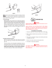
CONNECTION OF GAS PIPE
1. When connecting gas pipe to unit, apply wrench to flange
only. Note: Do not use wrench on gas valve or gas valve
bracket.
2. PERFORM THE GAS LEAK TEST ANY TIME WORK IS DONE
ON A GAS SYSTEM TO AVOID THE POSSIBILITY OF FIRE OR
EXPLOSION WITH PROPERTY DAMAGE, PERSONAL
INJURY, OR LOSS OF LIFE.
The Gas Leak Test is performed as follows: Paint pipe
connections upstream of gas control with a rich soap and
water solution to test for leaks before operating main burner.
Bubbles indicate gas leak. To stop leak, tighten pipe
connections. After piping connections are checked, turn on
main burner. (See Lighting and Operating Installations in
this manual or on water heater.) With main burner in operation,
paint pipe joints (including flanges), pilot gas tubing
connections and control inlet and outlet with rich soap and
water solution. Bubbles indicate gas leak. To stop leak,
tighten flange screws, joints and pipe connections. Replace
part if leak can't be stopped.
DISCONNECT THE APPLIANCE AND ITS INDIVIDUAL SHUT
OFF VALVE FROM THE GAS SUPPLY PIPING SYSTEM DURING
ANY SUPPLY PRESSURE TESTING EXCEEDING 1/2 PSI (3.5
kPa). GAS SUPPLY LINE MUST BE CAPPED WHEN
DISCONNECTED FROM THE HEATER. FOR TEST
PRESSURES AT 1/2 PSI (3.5 kPa) OR LESS, THE APPLIANCE
NEED NOT BE DISCONNECTED, BUT MUST BE ISOLATED
FROM THE SUPPLY PRESSURE TEST BY CLOSING THE MAIN
MANUAL GAS VALVE.
BEFORE PLACING THE HEATER IN OPERATION, CHECK FOR
GAS LEAKAGE. USE SOAP AND WATER SOLUTION OR OTHER
MATERIAL ACCEPTABLE FOR THIS PURPOSE. DO NOT USE
MATCHES CANDLES, FLAME OR OTHER SOURCES OF
IGNITION TO LOCATE GAS LEAKS.
RELIEF VALVE
A NEW TEMPERATURE AND PRESSURE RELIEF VALVE
COMPLYING WITH THE STANDARD FOR RELIEF VALVES AND
AUTOMATIC GAS SHUT OFF DEVICES FOR HOT WATER
SUPPLY SYSTEMS, ANSI Z21.22 (LATEST EDITION) MUST BE
INSTALLED IN THE HEATER IN THE MARKED OPENING
PROVIDED. THE VALVE MUST BE OF A SIZE (INPUT RATING)
THAT WILL BE ADEQUATE FOR YOUR SIZE HEATER.
Check the metal tag on the relief valve and compare it to the
heater’s rating plate. The pressure rating of relief valve must not
exceed the working pressure shown on the rating plate of the
heater. In addition the hourly Btu rated temperature steam
discharge capacity of the relief valve shall not be less than the
input rating of the heater. NO VALVE IS TO BE PLACED
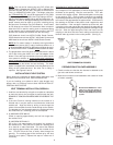
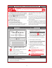
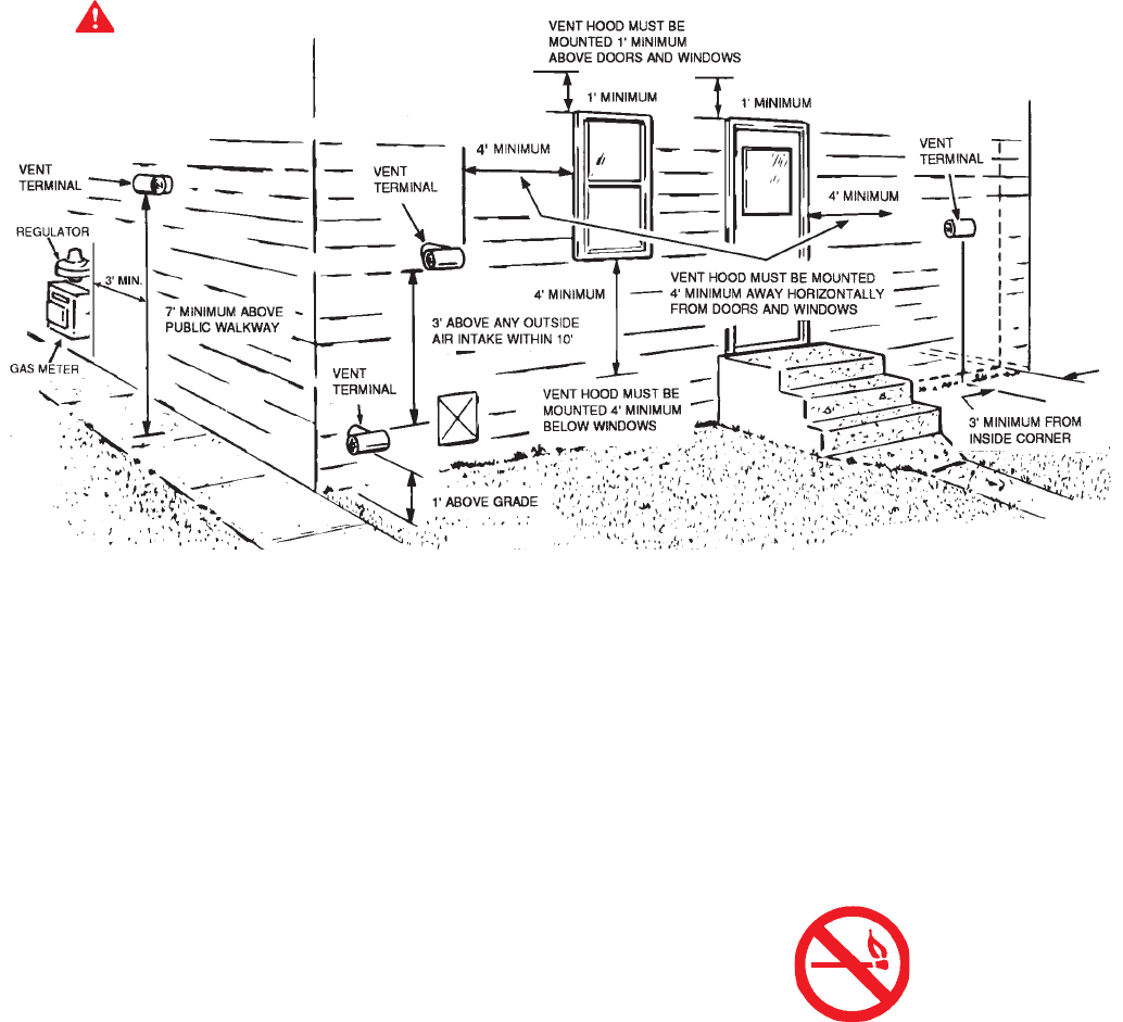
FIGURE 3
WARNING
VENT HOOD(S) MAY BE
EXTREMELY HOT
DURING OPERATION.