


5
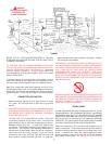
CONFINED SPACE
When drawing combustion and dilution air from inside a
conventionally constructed building to a confined space, such a
space shall be provided with two permanent openings. ONE
WITHIN 12 INCHES OF THE ENCLOSURE TOP AND ONE
WITHIN 12 INCHES OF THE ENCLOSURE BOTTOM. Each
opening shall have a free area of one square inch per 1000 Btuh
of the total input of all appliances in the enclosure, but not less
than 100 square inches.
If the confined space is within a building of tight construction, air
for combustion, ventilation and power venter dilution must be
obtained from outdoors. When directly communicating with the
outdoors or communicating through vertical ducts, two
permanent openings, located in the above manner, shall be
provided. Each opening shall have a free area of not less than
one square inch per 4000 Btuh of the total input of all appliances
in the enclosure. If horizontal ducts are used, each opening
shall have a free area of not less than one square inch per 2000
Btuh of the total input of all appliances in the enclosure.
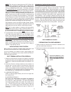
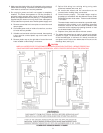
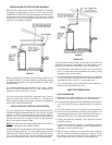
WATER CONNECTIONS
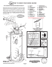
Refer to figure 1 for typical installation. A suitable pipe thread
sealant must be used to prevent leakage.
WATER (POTABLE) HEATING AND SPACE HEATING
1. All piping components connected to this unit for space heating
applications shall be suitable for use with potable water.
2. Toxic chemicals, such as those used for boiler treatment,
shall NEVER be introduced into this system.
3. This unit may NEVER be connected to any existing heating
system or component(s) previously used with a non-potable
water heating appliance.
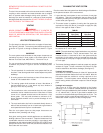
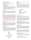
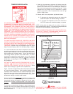
4. When the system requires water for space heating at
temperatures higher than required for domestic water
purposes, a tempering valve must be installed. Please refer
to Fig. 2 for suggested piping arrangement.
FIGURE 2
CLOSED WATER SYSTEM
A closed system will exist if a back-flow preventer (check valve),
pressure reducing valve, or other similar device is installed in
the cold water line between the water heater and the street main
(or well). Excessive pressure may develop due to the thermal
expansion of heated water causing premature tank failure or
intermittent relief valve operation. This type of failure is not
covered by the limited warranty. An expansion tank may be
necessary in the cold water supply to alleviate this situation, see
Fig. 1. Contact the local plumbing authority.
If the temperature and pressure relief valve on the appliance
discharges periodically, this may be due to thermal expansion
in a closed water supply system. Contact the water supplier or
local plumbing inspector on how to correct situation. DO NOT
PLUG THE TEMPERATURE AND PRESSURE RELIEF VALVE.
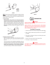
GAS CONNECTIONS
The minimum gas supply pressure for input adjustment is 5.0"
W.C. for natural gas (11.0" W.C. for propane).
THE HEATER IS NOT INTENDED FOR OPERATION AT HIGHER
THAN 14" WATER COLUMN SUPPLY PRESSURE. EXPOSURE
TO HIGHER GAS SUPPLY PRESSURE MAY CAUSE DAMAGE
TO THE CONTROL WHICH COULD RESULT IN FIRE OR
EXPLOSION. If overpressure has occurred such as through
improper testing of gas lines or emergency malfunction of the
supply system, the control must be checked for safe operation.
Make sure that the outside vents on the supply regulators and
the safety vent valves are protected against blockage. These
are parts of the gas supply system not the heater. Vent blockage
may occur during ice storms.
IT IS IMPORTANT TO GUARD AGAINST CONTROL FOULING
FROM CONTAMINANTS IN THE GAS WAYS. SUCH FOULING
MAY CAUSE IMPROPER OPERATION, FIRE OR EXPLOSION.
All piping must comply with local codes and ordinances or with
the National Fuel Gas Code (ANSI Z223.1 NFPA-54) whichever
applies.