


8
IMPORTANT
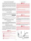
The vent system must terminate so that proper clearances are maintained
as cited in local codes or the latest edition of the National Fuel Gas Code,
ANSI Z223.1,7.3.4e and 7.8a,b, as follows:
1. Do not terminate the exhaust vent terminal over public area where
condensate or vapor can cause nuisance or hazard.
2. For direct vent, the venting system shall terminate at least 1 foot below,
1 foot horizontally from or 1 foot above any door, window, or gravity air
inlet into building.
3. For horizontal the venting system shall terminate 4 foot below, 4 foot
horizontally from or 1 foot above any door, window, or gravity air inlet
into building.
4. The manufacturer also recommends the vent system terminations not
be installed closer than 3 feet from an inside corner of an L shaped
structure. And not less than 1 foot above grade or anticipated snow
level.
5. The vent termination shall not be mounted directly above or within 3 feet
horizontally from an oil tank vent or gas meter to avoid potential freeze-
up from condensation.
6. The vent shall terminate a minimum of 12" above expected snowfall
level to prevent blockage of vent termination.
Plan the vent system layout so that proper clearances are maintained from
plumbing and wiring.
Vent pipes serving power vented appliances are classified by building
codes as "vent connectors". Required clearances from combustible
materials must be provided in accordance with information in this manual
under LOCATION OF HEATER and CLEARANCES, and with National Fuel
Gas Code and local Codes.
IMPORTANT
Plan the layout of the vent system backwards from the vent termination to
the appliance.
WARNING
USE ONLY THE VENT TERMINALS SUPPLIED WITH THIS UNIT. TERMINATION
OF A VENT SYSTEM WITH A DEVICE OTHER THAN THE SUPPLIED VENT
TERMINATIONS WILL AFFECT SYSTEM PERFORMANCE AND RESULT IN A
SAFETY HAZARD.
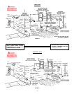
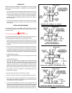
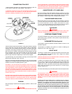
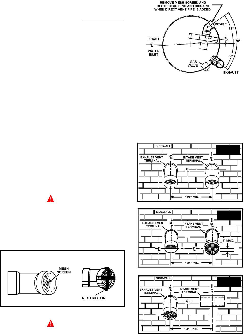
DIRECT VENTING
The air intake provided on the unit contains a mesh screen (see Figure 7)
to prevent large particles from entering the unit.
FIGURE 7
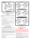
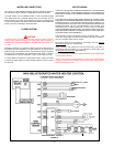
WARNING
WHEN THE UNIT IS TO BE SETUP AS A DIRECT VENT, THE MESH SCREEN
MUST BE REMOVED. THE INLET VENT PIPE MAY THEN BE GLUED TO THE
AIR INTAKE (see Figure 8) PROVIDED ON THE UNIT.
FIGURE 8
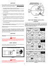
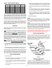
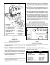
DIRECT VENT TERMINAL INSTALLATION
IMPORTANT
THIS UNIT CONSISTS OF TWO VENT TERMINALS - AN INTAKE VENT
TERMINAL AND AN EXHAUST VENT TERMINAL. THE INTAKE VENT
TERMINAL IS A 3" 45°PVC ELBOW (OR 3" PVC TEE FOR BTH 250) WITH A
MESH WIRE SCREEN AND THE EXHAUST VENT TERMINAL IS A 3" 45°PVC
ELBOW WITH A MESH WIRE SCREEN.
FIGURE 9
3" 45° PVC ELBOW WITH MESH SCREEN
BTH 120
BTH 150
& 199
BTH 250