


3
Water Line Connections.................................................................. 14
Heater Wiring .................................................................................. 14
OPERATION ......................................................................................... 15
Sequence of Operation ................................................................... 15
Self Diagnostic Controller ............................................................... 15
Gas Value LEDs Flashing ............................................................... 15
Error Codes ..................................................................................... 16
Fault Conditions .............................................................................. 16
No Incoming Line Voltage ............................................................... 16
No Low Voltage ............................................................................... 16
Temperature Probe Fault ................................................................. 16
E.C.O. Switch Open........................................................................ 17
Control Bad ..................................................................................... 17
Combustion Air Blockage................................................................ 17
PRIOR TO START-UP .......................................................................... 18
Required Ability ............................................................................... 18
OPERATIING INSTRUCTIONS ............................................................. 18
Adjustment Procedure (Initial Start-Up)........................................... 18
Lighting Instructions ........................................................................ 19
Cathodic Protection ......................................................................... 20
Precautions...................................................................................... 20
GENERAL INFORMATION .................................................................... 20
Power Burner ................................................................................... 20
High Limit ........................................................................................ 20
High Altitude Installations................................................................ 20
MAINTENANCE ..................................................................................... 20
General ............................................................................................ 20
Maintenance Schedule..................................................................... 20
Flushing ........................................................................................... 21
Draining ........................................................................................... 21
Sediment Removal.......................................................................... 21
Lime Scale Removal ....................................................................... 21
Anode Inspection and Replacement................................................ 21-22
Drain Valve and Access Panels ...................................................... 22
Relief Valve ..................................................................................... 22
Circulating Pump ............................................................................. 22
Vent System ................................................................................... 22
INSTALLATION DIAGRAMS................................................................... 23 - 27
Manifold Kits.................................................................................... 28
CHECKLIST AND SERVICE INFORMATION ....................................... 29
TROUBLE-SHOOTING .......................................................................... 29-30
REPLACEMENT PARTS ......................................................................... 30
LIMITED WARRANTY ......................................................................... 31
PAGE
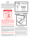
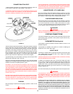
These designs comply with the latest version of the American National
Standard for Gas Water Heaters, Volume III, ANSI Z21.10.3 as an automatic
circulating tank water heater, and automatic storage water heaters.
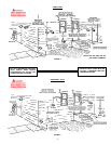
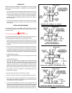
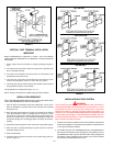
Detailed installation diagrams are found in this manual. These diagrams will
serve to provide the installer with a reference for the materials and methods
of piping necessary. It is highly essential that all water, gas piping and
wiring be installed as shown on the diagrams.
Particular attention should be given to the installation of thermometers at
the locations indicated on the diagrams as these are necessary for checking
the proper functioning of the heater.
In addition to these instructions, the equipment shall be installed in
accordance with those installation regulations in force in the local area
where the installation is to be made. These shall be carefully followed in all
cases. Authorities having jurisdiction should be consulted before
installations are made.
In the absence of local codes, the installation must comply with the latest
editions of the National Fuel Gas Code, ANSI Z223.1/NFPA 54 and the
National Electric Code, NFPA 70. The former is available from the
Canadian Standards Association, 8501 East Pleasant Valley Road,
Cleveland, OH 44131, and both documents are available from the National
Fire Protection Association, 1 Batterymarch Park, Quincy, MA 02269.
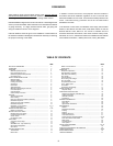
TABLE OF CONTENTS
PAGE
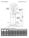
ROUGH-IN DIMENSIONS................................................................... 2
FOREWORD ....................................................................................... 3
FEATURES........................................................................................... 4
Water Temperature Control ............................................................. 4
High Limit Switch (E.C.O.).............................................................. 4
Dishwashing Machine Requirement ................................................ 5
Circulating Pump............................................................................. 5
INSTALLATION INSTRUCTIONS ......................................................... 5
Required Ability............................................................................... 5
Insulation Blankets.......................................................................... 5
Locating The Heater........................................................................ 5
Clearances ...................................................................................... 6
Hard Water...................................................................................... 6
Air Requirements ............................................................................ 6
Mechanical Exhausting of Room Air............................................... 6
Unconfined Space .......................................................................... 6
Confined Space .............................................................................. 6
Chemical Vapor Corrosion .............................................................. 6
VENTING ............................................................................................. 6
Vent Pipe Termination ..................................................................... 6
Direct Venting ................................................................................. 8
Direct Vent Terminal Installation (Sidewall) ..................................... 8
Installation Sequence ...................................................................... 9
Vertical Vent Terminal Installation ................................................... 10
Installation Sequence ...................................................................... 10
Installation of Vent System............................................................ 10 -11
Vent Pipe Preparation ..................................................................... 11
CONTROLS AND SWITCHES............................................................. 11-12
Blower Prover Switch ...................................................................... 11
Blocked Outlet Prover Switch .............................................................. 12
Blocked Inlet Prover Switch............................................................ 12
Low Gas Pressure Switch ............................................................... 12
On/Off Switch ................................................................................. 12
Hot Surface Igniter ......................................................................... 12
GAS PIPING ........................................................................................ 12
Connection of Gas Pipe.................................................................. 13
Purging ............................................................................................ 13
Gas Meter Size - City Gases Only ................................................. 13
Gas Pressure Regulation ................................................................ 13
Gas Valves...................................................................................... 13
SYSTEM CONNECTIONS ................................................................... 13
Thermometers ................................................................................. 13
Relief Valve .................................................................................... 13
FOREWORD