


10
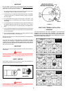
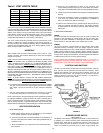
FIGURE 12
INSTALLATION OF VENT SYSTEM
WARNING
THE OPTIONAL INTAKE VENTING ARRANGEMENT AND THE EXHAUST
VENTING ARRANGEMENT MUST BE INSTALLED TO RUN DIRECTLY TO THE
OUTDOORS AND NOT IN ANY WAY BE CONNECTED TO ANOTHER
VENTING SYSTEM (I.E. FURNACE, DRYERS OR SPACE HEATERS). IT IS
CRUCIAL THAT THE VENTING ARRANGEMENT BE KEPT SEPARATE FROM
OTHER VENTING SYSTEMS. IF THIS WARNING IS IGNORED, AND THE
SYSTEM IS VENTED INCORRECTLY, IT MAY CAUSE IMPROPER OPERATION,
FIRE, EXPLOSION, OR ASPHYXIATION.
1. Plan the route of the vent system from the vent termination to the planned
location of the appliance. Layout the total vent system to use the minimum
of vent pipe and elbows possible.
2. The installer may add up to a MAXIMUM OF FIFTY (50) EQUIVALENT
feet of pipe to the exhaust venting arrangement. This addition of FIFTY
(50) EQUIVALENT feet of pipe on both the intake venting arrangement
and exhaust venting arrangement must include any 3 inch PVC elbows
which equals (5) EQUIVALENT feet of pipe.
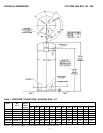
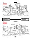
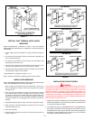
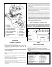
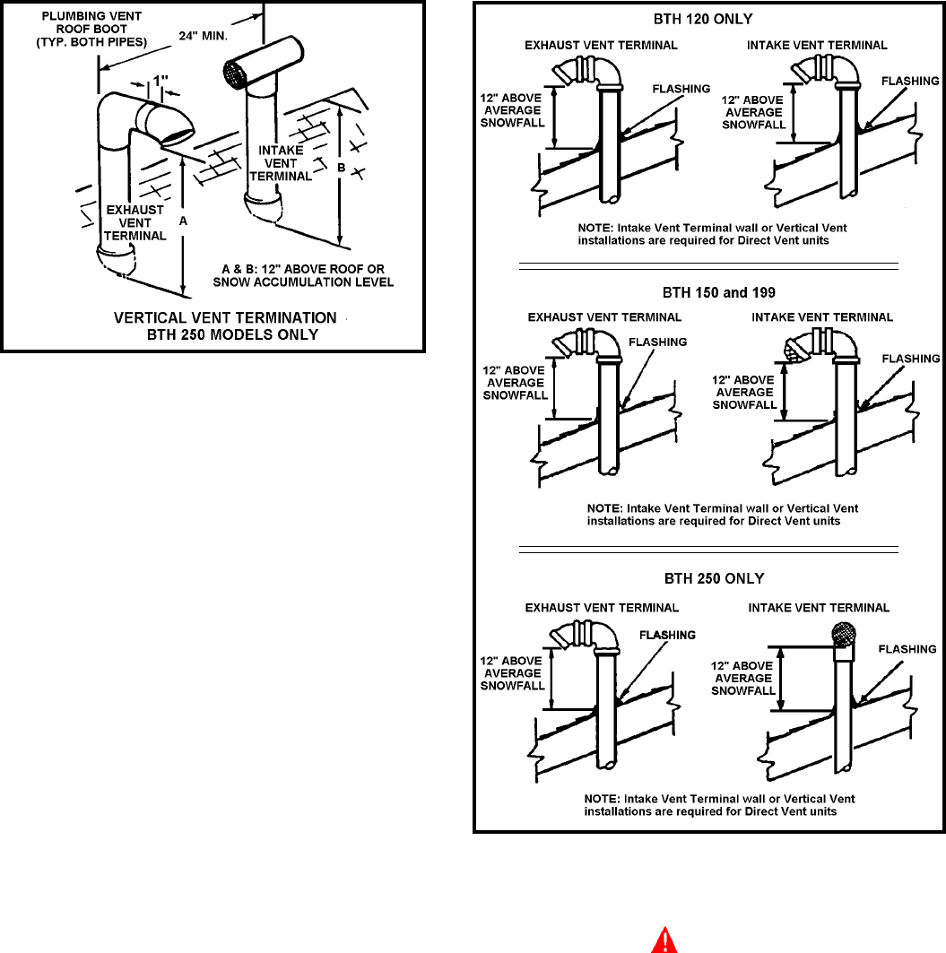
FIGURE 11
VERTICAL VENT TERMINAL INSTALLATION
IMPORTANT
WHEN TERMINATING THROUGH A ROOF, THE FOLLOWING
SPECIFICATIONS PERTAINING TO TERMINAL LOCATION MUST BE
FOLLOWED.
1. Proper support must be provided for all pipe protruding through the
roof.
2. The vertical roof terminations should be sealed with a plumbing roof
boot or equivalent flashing.
3. The intake vent termination and the exhaust vent termination must
penetrate the same side of roof.
4. The center line of the intake vent termination and the center line of the
exhaust vent termination must be no closer than 24" (inches).
5. The intake vent terminal and the exhaust vent terminal must be oriented
facing downward and the same direction.
The specifications are displayed in Figure 11 & 12.
NOTE: Exhaust vent terminal is installed using the same procedure.
INSTALLATION SEQUENCE
NOTE: BEFORE BEGINNING INSTALLATION OF ANY VENT PIPE, READ
“VENT PIPE PREPARATION” SECTION ON PAGE 11.
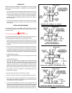
1. After the points of termination have been determined, use the cover
plates as templates to mark the holes for the vent pipes to be inserted
through the roof.
2. Drill a pilot hole approximately one quarter inch outside of the marked
circle. This pilot hole is used as a starting point for a saws-all or sabre
saw blade. Cut around the marked circle staying approximately one
quarter inch outside the line. (This will allow the vent pipe to easily slide
through the opening). The resulting gap will be covered by the roof boot/
flashing.
3. Suspend the pipe through the center of the hole using proper support.
4. Slide roof boot or equivalent flashing over pipe and secure roof boot
equivalent flashing to roof.
5. Seal around flashing.
6. Terminate intake terminal and exhaust vent terminal facing down as
shown in Figure 12.