


18
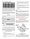
ADJUSTMENT PROCEDURE
INITIAL START-UP
A minimum gas supply pressure of 5.0" W.C. (4.5" on BTH 150 and 199) for
natural gas (11.0" W.C. for L.P. Gas) is required before making any
adjustment to the gas control pressure regulator Attempts to adjust the
regulator during periods of low gas supply pressure could result in overfiring
of the heater when the gas supply pressure returns to normal.
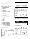
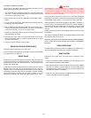
1. Check gas line pressure with a manometer.
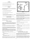
2. Check manifold pressure (see Table 4, page 20) using a pressure
gauge (manometer) connected to the manifold pressure tap on the
gas control valve, (Figure15).
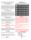
If full rate adjustment is required, remove cover screw from top of the
gas control valve, (Figure 15).
Using a small screwdriver, turn adjusting screw clockwise to increase
or counterclockwise to decrease gas pressure to obtain 4.0" on
BTH 120 and 250 (3.5" on BTH 150 and 199) for natural gas (10.0" W.C.
for L.P. Gas) Water Column.
3. Cycle the burner on and off several times to check its operation.
4. Check the operation of the limit and operating controls.
5. Check the vent system seams and joints and ensure that there is no
discharge of flue products into the room.
6. Check the input rate:
For appliance installation locations with elevations above 2000 feet, refer
to HIGH ALTITUDE INSTALLATIONS section of this manual.
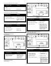
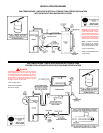
a. Attach a pressure gauge (manometer) to the manifold pressure tap
(Figure 16) and refer to Table 4, page 20 for correct pressure.
b. Use this formula to clock the meter. Be sure other gas consuming
appliances are not operating during this interval.
3600
X H = Btuh
T
Should it be necessary to adjust the gas pressure to the burner, to obtain
the full input rate, the steps below should be followed:
T = Time in seconds to burn 1 cubic foot of gas. (With a stopwatch read
the gas meter and measure the amount of time required for the
heater to consume 1 cubic foot of gas.)
H = Heating value of gas (in Btus per cubic foot of gas).
Btuh = Actual heater input rate, in Btuh.
EXAMPLE: (Using BTH-199,900 heater)
T = 18.9 seconds
H = 1050 Btu/ft.
3
BTUH = ?
For high altitude installations, compare result to the derated input
required for the elevation at the installation location.
c. Remove the pressure regulator cover screw (Figure 16) and adjust
the pressure by turning the adjusting screw with a small
screwdriver. Do not exceed 4.0" on BTH 120 and 250 (3.5" on BTH
150 and 199) Water Column.
Clockwise to increase gas pressure and input rate.
Counterclockwise to decrease gas pressure and input rate.
d. Clock the meter as in step (b) above.
e. Repeat steps (c) and (d) until the specified input rate is achieved.
f. Turn the manual gas valve to OFF. Replace the pressure regulator
cover screw. Remove the pressure gauge or manometer from the
manifold pressure tap. Replace the set screw in the manifold pressure
tap. If the gas pressure regulator cannot be adjusted to give the full
input rating with sufficient gas pressure at the valve, check to ensure
the unit is equipped with the correct orifice.
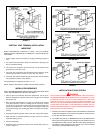
PRIOR TO START UP
REQUIRED ABILITY
INSTALLATION OR SERVICE OF THIS WATER HEATER REQUIRES ABILITY
EQUIVALENT TO THAT OF A LICENSED TRADESMAN IN THE FIELD
INVOLVED. PLUMBING, AIR SUPPLY, VENTING, GAS SUPPLY AND
ELECTRICAL WORK ARE REQUIRED.
Before attempting start-up, thoroughly study and familiarize yourself with
the exact sequence of operation and all other details on the specific heater
being used.
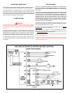
The power burner is equipped with an ignition system which automatically
sequences prepurge and ignition, senses and ignites main burner flame
and sequences burner operation. Heater is equipped with an ignition control
which locks out after three unsuccessful ignition attempts. Familiarize
yourself with the sequence of operation of this unit prior to start-up.
Be certain that the water heater is full of water, that air is purged from all
lines, there are no leaks (gas and water), and all inlet water lines are open.
The following test equipment should be on hand (all test equipment must be
acclimated to ambient temperature before calibration and use.)
Two U-tube manometers or calibration 0-10" and 0-35" W.C. pressure
gauges.
Attach a gas pressure gauge or manometer to the upstream side of
main gas cock and a gas pressure gauge or manometer to the manifold
pressure tap (see Figure 15).
You are now ready to begin the burner start-up procedure.
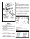
OPERATING INSTRUCTIONS
IMPORTANT
IT IS RECOMMENDED THAT A QUALIFIED SERVICE TECHNICIAN PERFORM
THE INITIAL FIRING OF THE HEATER. AT THIS TIME THE USER SHOULD ASK
THE TECHNICIAN ANY QUESTIONS IN REGARD TO THE OPERATION AND
MAINTENANCE OF THE UNIT.
CAUTION
BEFORE PROCEEDING WITH THE OPERATION OF THE UNIT, MAKE SURE
HEATER AND SYSTEM ARE FILLED WITH WATER AND ALL AIR IS EXPELLED
FROM HEATER AND PIPING.
NEVER OPERATE THE HEATER WITHOUT FIRST BEING CERTAIN IT IS FILLED
WITH WATER AND A TEMPERATURE AND A PRESSURE RELIEF VALVE IS
INSTALLED IN THE RELIEF VALVEOPENING OF THE HEATER. DO NOT
ATTEMPT TO OPERATE HEATER WITH COLD WATER INLET VALVE CLOSED.
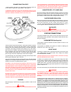
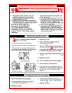
FILLING:
1. Close the heater drain valve.
2. Open a nearby hot water faucet to permit the air in the system to
escape.
3. Fully open the cold water inlet pipe valve allowing the heater and
piping to be filled.
4. Close the hot water faucet as water starts to flow.
5. The heater is ready to be operated.
THE MAIN MANUAL GAS SHUTOFF VALVE MUST HAVE BEEN CLOSED
FOR AT LEAST FIVE (5) MINUTES. THIS WAITING PERIOD IS AN IMPORTANT
SAFETY STEP. ITS PURPOSE IS TO PERMIT GAS THAT MIGHT HAVE
ACCUMULATED IN THE COMBUSTION CHAMBER TO CLEAR. IF YOU DETECT
GAS AT THE END OF THIS PERIOD, DO NOT PROCEED WITH LIGHTING.
RECOGNIZE THAT GAS ODOR, EVEN IF IT SEEMS WEAK, MAY INDICATE
THE PRESENCE OF ACCUMULATED GAS SOMEPLACE IN THE AREA WITH
A RISK OF FIRE OR EXPLOSION. SEE THE FRONT PAGE FOR STEPS TO BE
TAKEN.
DO NOT USE THIS HEATER IF ANY PART HAS BEEN UNDER WATER.
IMMEDIATELY CALL A QUALIFIED SERVICE TECHNICIAN TO INSPECT THE
HEATER AND TO REPLACE ANY PART OF THE CONTROL SYSTEM AND
ANY GAS CONTROL WHICH HAS BEEN UNDER WATER.
LIGHT THE UNIT IN ACCORDANCE WITH THE OPERATING INSTRUCTIONS
LABEL ATTACHED TO THE HEATER.
THESE INSTRUCTIONS ARE REPEATED IN THE LIGHTING AND OPERATING
LABEL ILLUSTRATION ON PAGE 20 IN THIS MANUAL.
3600
X 1050 = 199,900 Btuh
18.9