


Installation
24 Instruction manual BFC
3
is
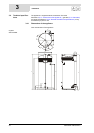
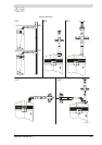
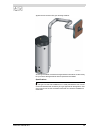
3.6 Water connections,
Unvented
Warning
The installation should be carried out by an authorised installation engineer,
in compliance with general and local regulations (1.3 "Regulations").
3.6.1 Cold water side
See (A) in the installation diagram (3.5 "Installation diagram").
1. Fit an approved stop valve (4) on the cold water side as required by
applicable regulations (1.3 "Regulations").
2. The maximum working pressure of the appliance is 8 bar. Because the
pressure in the water pipe at times can exceed 8 bar, you must fit an
approved pressure-reducing valve (1).
3. Fit a non-return valve (5) and an expansion vessel (16).
4. Fit an expansion valve (15) and connect the overflow side to an open
wastewater pipe.
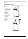
3.6.2 Hot water side
See (B) in the installation diagram (3.5 "Installation diagram").
Note
Insulating long hot water pipes will prevent unnecessary energy loss.
1. Optional: fit a temperature gauge (12) so you can check the temperature of
the tap water.
2. Fit the T&P valve (3).
3. Fit a stop valve (11) in the hot water outlet pipe for servicing.
3.6.3 Circulation pipe
See (C) in the installation diagram (3.5 "Installation diagram").
If an immediate flow of hot water is required at draw-off points, a circulation
pump can be installed. This improves comfort and reduces water wastage.
1. Fit a circulation pump (6) of the correct capacity for the length and resistance
of the circulation system.
2. Fit a non-return valve (5) behind the circulation pump to guarantee the
direction of circulation.
3. Fit two stop valves for service purposes (4).
4. Connect the circulation pipe to the cold water supply pipe.
3.6.4 Condensation drainage
1. Fit a sloping wastewater pipe to the siphon (13) for condensation drainage
and connect this to the wastewater discharge in the boiler room.
Attention
All fittings behind the siphon must be condensation-resistant.