


Working principle of the appliance
14 Instruction manual BFC
2
gis
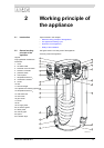
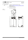
In this appliance the cold water enters the bottom of the tank via the cold water
inlet (14). Once heated by the combustion chamber (8) and heat exchanger
(11), the hot tapwater leaves the tank through the hot water outlet (2). Once the
appliance is completely filled with water, it remains constantly under water
supply pressure. As hot water is drawn from the appliance, it is immediately
replenished with cold water.
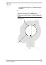
The air required for combustion is forced into the burner (17) by the fan (18).
The gas is fed to the burner via the gas valve (16). Thanks to the modulated
supply of gas and air, the optimum gas/air mixture is always achieved. The
special construction of the burner causes the mixture to form a vortex (the
cyclone effect), before it becomes ignited. This vorticity improves the ignition on
the hot surface igniter (20), as well as ensuring optimum combustion efficiency.
Through the special design of the heat exchanger (11), the flue gases are first
led downwards via the combustion chamber, then upwards again via the heat
exchanger, then once more downwards beside the water in the tank. In this
process, the flue gases gradually become cooler. Because the cooled flue
gases flow alongside the cold water lower down in the tank, they start to
condense. This condensation causes latent heat energy to be released, which
is transferred to the cooler water, thereby increasing the energy performance of
the unit. The condensate yielded by this process is discharged via the siphon
(23).
The insulation layer (24) prevents heat from escaping. The inside of the tank is
enamelled to protect against corrosion. The anodes (9) provide extra protection
against corrosion.
For use during maintenance, the appliance has an inspection and cleaning
opening (12).
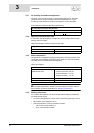
2.3 The appliance's
heating cycle
The water temperature is measured by temperature sensors T1 (7) in the top of
the tank (10) and T2 (13) at the bottom of the tank. These temperatures are sent
to the electronic controller. Based on these two observations, the electronic
controller calculates a net water temperature: T
net
. The value of T
net
lies
between the temperatures at the top and bottom of the tank. As soon as
Tnet
falls below the set water temperature (T
set
), the electronic controller registers a
"heat demand". The gas control (16) is opened, and the gas is mixed with air.
This mixture is ignited by the hot surface igniter (20) and the water becomes
heated. As soon as
Tnet
rises above T
set
the heat demand ends, and the
electronic controller stops the heating cycle.
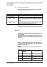
The electronic controller assumes a certain margin both when registering and
ending heat demand. We refer to this margin as the hysteresis (12.2 "Setting
the hysteresis").
2.4 Protection for the
appliance
2.4.1 Introduction
The electronic controller monitors the water temperature and ensures safe
combustion. This is achieved by:
• the Water temperature protection;
•theGas valve;
• the Fan;
• the Pressure switch;
• the Flame probe.