


Installation
22 Instruction manual BFC
3
is
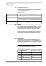
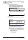
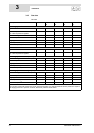
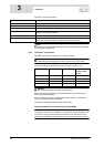
3.4.3 Gas data
Gas data
Description II
2H3+
Unit BFC
28
BFC
30
BFC
50
BFC
60
Gas category 2H: G20 - 20 mbar
Injector orifice diameter mm 4.90 5.10 7.00 7.10
(1) = Blank plate
(2) = Burner pressure regulator
1 or 2 2 2 2 2
Nominal load (gross calorific value) kW 32.1 34.5 52.6 63.2
Nominal output kW 30.5 32.7 48.8 59.6
Supply pressure mbar 20 20 20 20
Burner pressure mbar 8.5 8.5 8.5 11.5
Gas consumption
(*)
m
3
/h 3.1 3.3 5.0 6.0
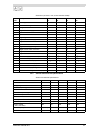
General 3+
Injector orifice diameter mm 2.50 2.60 3.40 3.80
(1) = Blank plate
(2) = Burner pressure regulator
1 or 2 1 1 1 1
Gas category: G30-30 mbar (butane)
Nominal load (gross calorific value) kW 30.7 32.8 50.6 59.4
Nominal output kW 29.8 31.8 48.1 57.4
Supply pressure mbar 30 30 30 30
Burner pressure
(†)
mbar----
Gas consumption
(*)
kg/h 2.2 2.4 3.7 4.3
Gas category: G31-37 mbar (propane)
Nominal load (gross calorific value) kW 29.0 30.9 50.3 59.1
Nominal output kW 28.1 29.8 47.7 56.9
Supply pressure mbar 37 37 37 37
Burner pressure
(†)
mbar----
Gas consumption
(*)
kg/h 2.1 2.2 3.6 4.2
(*) Based on 1013.25 mbar and 15 °C.
(†) If using a blank plate instead of a burner pressure regulator, it is assumed that the burner pressure is equal to
the supply pressure. In practice, however, the burner pressure will be lower.