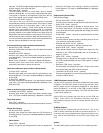
31
Fuse Protection
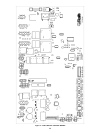
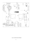
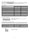
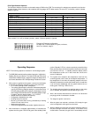
The 24VAC circuitry is protected with a 3 amp fuse on the Flame
Control Boards (FCB) and a 7.5 amp fuse on the Central Control
Board. If the fuse opens, a red LED located near the fuse will light.
See Figures 17 and 18. If the red LED is illuminated, replace the
fuse. Repeated failure of the fuse is an indication of possible
damage to the ignition control. The 120VAC circuits of each Flame
Control Board is protected with a 10 amp (15 amp for the CCB)
fuse located on the Power Distribution Board (PDB). The 20 amp
pump fuse is also on the PDB.
Recommended Replacement fuses:
Littlefuse automotive fuse p/n 29707.5 for the 7.5 amp
CCB fuse, and Littlefuse p/n 297003 for the 3 amp FCB fuses.
OPERATION
IMPORTANT
Only qualified personnel shall perform the initial firing of the heater.
If you have questions, please contact the factory or your local A.O.
Smith representative.
Operation and troubleshooting instructions are included with this
manual. By using these instructions, the user may be able to
make minor operational adjustments. The user should not attempt
repairs, but should contact a service technician or gas supplier
for service.
GENERAL
Never operate the boiler without first making sure the boiler and
system are filled with water, in addition:
For hot water supply Boiler installations:
• Make sure a temperature and pressure relief valve is installed
on the storage tank if used. Also check for leaks.
For heating boiler installations:
• Make sure that the boiler and system have been purged of air
and checked for leaks.
FILLING AND PURGING WATER SYSTEM
(A.) Hydronic Heating Installation:
1. Fill system through bypass until pressure approaches
desired system pressure. Close bypass valve and
permit pressure to be established by the pressure
reducing valve.
2. Vent all high points in system to purge system of air.
Provisions should be made to permit manual venting of radiators or
convectors.
(B.) Hot Water Supply Installation:
1. Close the systems drain valve.
2. Open a nearby hot water faucet to permit the air in the system
to escape.
3. Fully open the cold water inlet pipe valve allowing the heater
and piping to be filled.
4. Close the hot water faucet as water starts to flow.
5. The heater is ready to be operated.
PURGING OF GAS LINE
Gas line purging is required with new piping or systems in which
air has entered.
CAUTION
PURGING SHOULD BE PERFORMED BY PERSONS
EXPERIENCED IN THIS TYPE OF GAS SERVICE TO AVOID RISK
OF FIRE OR EXPLOSION. PURGE DISCHARGE MUST NOT
ENTER CONFINED AREAS OR SPACES WHERE IGNITION CAN
OCCUR. THE AREA MUST BE WELL VENTILATED AND ALL
SOURCES OF IGNITION MUST BE DEACTIVATED OR
REMOVED.
BEFORE PLACING THE BOILER IN OPERATION, CHECK FOR
GAS LEAKAGE. USE A SOAP AND WATER SOLUTION OR OTHER
MATERIAL ACCEPTABLE FOR THE PURPOSE OF LOCATING GAS
LEAKS. DO NOT USE MATCHES, CANDLES, FLAME OR OTHER
SOURCES OF IGNITION FOR THIS PURPOSE.
WARNING
THE GAS VALVE MUST HAVE BEEN IN THE OFF POSITION FOR AT
LEAST 5 MINUTES. This waiting period is an important safety
step. Its purpose is to permit gas that may have accumulated in
the combustion chamber to clear. IF YOU DETECT GAS ODOR AT
THE END OF THIS PERIOD DO NOT PROCEED WITH LIGHTING.
RECOGNIZE THAT GAS EVEN IF IT SEEMS WEAK, MAY INDICATE
PRESENCE OF ACCUMULATED GAS SOMEPLACE IN THE AREA
WITH RISK OF FIRE OR EXPLOSION. SEE THE FRONT PAGE
FOR STEPS TO BE TAKEN.
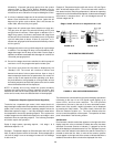
INLET GAS PRESSURE
The inlet gas pressure is measured by removing the low gas
pressure switch located on the main gas manifold which is
upstream of the unit's combination gas valves. See Figure 14. The
maximum value specified in the table must not be exceeded. The
minimum values, shown in Table 19, must be maintained under
both load and no load conditions (static and firing conditions). The
combination gas valves supplied with the boiler are for low pressure
service. If upstream pressure exceeds 14.0" W.C., an
intermediate gas pressure regulator of the lockup type must be
installed.
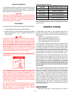
TABLE 19. INLET GAS PRESSURES.
INLET GAS PRESSURE NAT. GAS PROP. GAS
MAX. INLET PRESSURE (IN. W.C.) 14.0 14.0
MIN. INLET PRESSURE (IN. W.C.) 6.0 11.0


