3
FOREWORD
This design complies with the latest edition of the ANSI Standard
Z21.10.3 for gas water heaters Vol. III Storage Water Heaters
with input ratings above 75,000 BTU per hour Circulating and
Instantaneous.
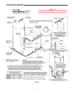
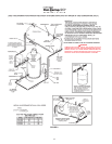
Detailed installation diagrams are in this manual. These diagrams
will serve to provide the installer with a reference for the materials
and method of piping suggested. IT IS ESSENTIAL THAT ALL
WATER AND GAS PIPING AND THE ELECTRICAL WIRING BE
INSTALLED AND CONNECTED AS SHOWN IN THE DIAGRAMS.
You should thoroughly read and understand this manual before
installation and operation of this unit.
CHECK THE DIAGRAMS THOROUGHLY BEFORE STARTING
INSTALLATION TO AVOID POSSIBLE ERRORS AND TO
MINIMIZE TIME AND MATERIALS COST.
Particular attention should be given to the installation of
thermometers at the locations indicated in the diagrams as these
are necessary for checking the operation of the heater.
MAKE SURE THE GAS ON WHICH THE HEATER WILL
OPERATE IS THE SAME AS THAT SPECIFIED ON THE HEATER
MODEL AND RATING PLATE.
The factory warranty will be void if the unit(s) have been improperly
installed or operated.
In addition to these instructions, the boiler(s) shall be installed in
accordance with those installation regulations in force in the local
area where the installation is to be made. These shall be carefully
followed in all cases. Authorities having jurisdiction should be
consulted before installations are made.
In absence of local codes, the installation must comply with the
latest editions.
I
n the United States:
The National Fuel Gas Code, ANSI Z223.1 and the National
Electric Code, NFPA 70.
In Canada:
The Installation Code CAN/CGA B149.1 and .2 (latest edition)
and the Canadian Electric Code, CSA C22.1.
These are available from the Canadian Standards Association,
8501 East Pleasant Valley Road, Cleveland, OH 44131, USA, or,
Canadian Gas Association Laboratories, 55 Scarsdale Road, Don
Mills, Ontario M3B 2R3, Canada.
TABLE OF CONTENTS
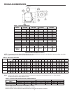
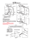
ROUGH-IN DIMENSIONS .................................................................. 2
FOREWORD....................................................................................... 3
GENERAL SAFETY INFORMATION .................................................. 3
Precautions .................................................................................... 3-4
Grounding Instructions ................................................................... 4
Chemical Vapor Corrosion ............................................................. 4
Liquid Petroleum Models ................................................................ 4
High Altitude Installations ............................................................... 4
FEATURES ......................................................................................... 5
Automatic Gas Shutoff Control ....................................................... 5
Protector Switch (Coil High Limit)................................................... 5
Thermal Balancer........................................................................... 5
Intermittent Ignition Control Module ................................................ 5-6
Circulating Pump............................................................................ 6
Tank Temperature Control (Not Supplied) ...................................... 6
Safety Flow Switch (Not Supplied) ................................................. 6-7
Drain Valve (Not Supplied) ............................................................. 7
Thermometers (Not Supplied) ........................................................ 7
INSTALLATION INSTRUCTIONS ....................................................... 8
Important ........................................................................................ 8
Required Ability .............................................................................. 8
Location ......................................................................................... 8
Installation Clearances ................................................................... 8
Levelling ......................................................................................... 8
Air Requirements ........................................................................... 8-9
Venting ........................................................................................... 9
Relief Valve .................................................................................... 9-10
Hard Water..................................................................................... 10
Closed Water System .................................................................... 10
Water Line Connections ................................................................ 10
Water (Potable) Heating ................................................................ 10
PIPING DIAGRAMS ............................................................................ 11-13
Gas Connections ........................................................................... 14-15
Electrical Information..................................................................... 15-16
OPERATION ........................................................................................ 17
Important ....................................................................................... 17
General........................................................................................... 17
Filling.............................................................................................. 17
Purging Of Gas Line ...................................................................... 17
Operating Instructions For I.I.D Models. ....................................... 18
Checking And Adjusting The Input................................................. 19
SERVICE INFORMATION .................................................................. 20
Pilot And Main Burner Maintenance ............................................... 20
I.I.D. Pilot Burner ........................................................................... 20-21
Protector Switch (Coil High Limit-All Heaters) ............................... 21
Tank Temperature Control .............................................................. 21
Automatic Gas Shutoff Control ..................................................... 21
Thermal Balancer ........................................................................... 21
Inspecting The Heat Exchanger And Venting System .................. 21-22
Gas Pressure Regulator ................................................................ 22
Relief Valve ................................................................................... 22
Circulating Pump............................................................................ 22
Electrical Service ........................................................................... 22
Replacement Parts ........................................................................ 22
PREVENTIVE MAINTENANCE ........................................................... 22
Recommended Procedure For Periodic Removal Of Lime
Deposits From Coil Type Commercial Water Heaters ................. 22-23
Deliming Solvents.......................................................................... 23
Removing Light Deposits .............................................................. 23
Heavy Lime Deposits ................................................................... 23-24
CHECKOUT ........................................................................................ 24-27
LIMITED WARRANTY ........................................................................ 28
PAGE
PAGE
GENERAL SAFETY INFORMATION
PRECAUTIONS
If the unit is exposed to the following, do not operate heater until
all corrective steps have been made by a qualified serviceman:
1. FLOODING TO LEVEL OF BURNER OR CONTROLS OR
HIGHER.
2. EXPOSURE TO FIRE.
3. IF DAMAGED.
4. FIRING WITHOUT WATER.
5. SOOTING.
KEEP THE HEATER AREA CLEAR AND FREE FROM
COMBUSTIBLE MATERIALS, GASOLINE AND OTHER
FLAMMABLE VAPORS AND LIQUIDS. AREA AROUND HEATER
MUST NOT CONTAIN OBSTRUCTING MATERIAL TO THE
FLOW OF COMBUSTION AND VENTILATING AIR.


