17
mandatory but offers smooth, efficient operation of a modern
system.
Normal use of flow control valves is required to prevent cross
circulation of zones as with any multiple pump system.
Large systems with multiple boilers should include main water
temperature controls (with or without outdoor reset) to sequence
the boiler on and off, in relation to the load on the system.
24 VAC System Controller (Optional)
GB models require a field supplied 24VAC operating control to be
installed in the system such as: loop thermostat, indoor/outdoor
reset control, sequencing panel, or energy management system.
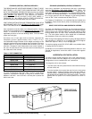
The connection for such devices is located in the 24 VAC junction
box at the rear of the unit. A 24 VAC thermostat/aquastat can only be
used as an "On/Off" switch for the unit. The actual controlling of the
staging will be through either the inlet or tank probe. To use a 24 VAC
system controller, dip switch "E" on the CCB must be switched to the
"on" position. See figure 14.
INTERNAL CONTAMINANTS
The system must be internally cleaned and flushed after a new or
replacement unit has been installed to remove contaminants that
may have accumulated during installation. This is doubly important
when a replacement unit is installed into an existing system where
Stop Leak or other boiler additives have been used.
All systems should be completely flushed with a grease removing
solution to assure trouble-free operation. Pipe joint compounds,
soldering paste, grease on tubing and pipe all tend to contaminate
a system.
Failure to clean and flush the system can cause solids to form on
the inside of the heat exchanger, can produce acid concentrations
that become corrosive, can allow excessive amounts of air or other
gases to form which could block circulation, foul system
accessories and damage circulator seals and impellers.
It is recommended that after installation, the boiler and system
when filled should include the proper percentage of cleaning
solution related to approximate water volume of the system. Fire
and circulate for about one hour and then flush clean with fresh
water. Commercial grease removing solutions are available.
Before operating the boiler, the entire system must be filled with
water, purged of air and checked for leaks. Do not use Stop Leak or
other boiler compounds. The gas piping must also be leak tested.
THE WATER HEATER SHOULD BE LOCATED IN AN AREA WHERE
THE GENERAL PUBLIC DOES NOT HAVE ACCESS TO SET
TEMPERATURES.
HOT WATER SUPPLY BOILER
INSTALLATION
WATER LINE CONNECTIONS
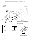
Where excessive heat exchanger condensation exists due to
continued low inlet water temperatures (below 120
o
F), a bypass
balance loop must be installed (see figures 11 and 13).
HARD WATER CONDITIONS
Where hard water conditions exist, water softening or the threshold
type of water treatment is recommended. This will protect the
dishwashers, coffee urns, water heaters, water piping and other
equipment. When water softening or water treatment is not practical,
a comparatively easy method of periodic lime removal from the unit
must be employed.
WARNING
LIME ACCUMULATION CAN REDUCE THE LIFE OF THE
EQUIPMENT, REDUCE EFFICIENCY AND WASTE FUEL. BOILER
FAILURE DUE TO LIME OR SCALE BUILDUP VOIDS THE
WARRANTY.
Tank Probe (Optional)
In addition to the Inlet and Outlet/ECO Probes, units can be
optionally equipped with a tank Probe. The connection for the tank
probe is located in the 24VAC junction box at the rear of the unit.
The tank Probe can be configured to control the staging of the unit.
See Tank Probe Installation section below for additional
information.
TANK PROBE INSTALLATION PROCEDURE
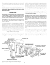
A tank probe is supplied with each hot water supply boiler (GW). To
connect the tank probe to the boiler, remove the cover from the 24
VAC junction box at the rear of the unit. Connect the probe wires
across terminals 1 & 2. (The wires leading to the terminals will be
yellow.) Check the field connection diagram located on this cover
of the junction box to assure proper wiring.
Once the tank probe has been connected to the boiler, it must be
designated as the controlling probe for the system. This is
accomplished by changing two Dip Switch settings on the Central
Control Board. First, Dip Switch "D" must be set to the "ON" position
to designate the tank probe as the controlling probe. Second, Dip
Switch "G" must be set to the "OFF" position to limit the maximum
tank probe temperature for GW applications. It is also advisable to
make sure Dip Switch "F" is set to the "OFF" position which sets the
Outlet temperature Set-Point to 210°F (99°C). See figure 14. Failure
to do this will void the warranty. If the tank probe is not designated
as the controlling probe, the staging of the unit will be controlled by
the Inlet Probe and will not use the desired tank temperature as its
base. Once the tank Probe is designated as the controlling probe,
the Inlet Water Temperature on the display will default to the tank
temperature.
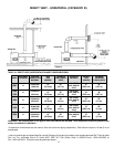
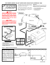
Refer to "Connection Diagram" (figure 20) and figure 12 in order to
connect the tank probe to the boiler.
See section titled "PROCEDURES FOR SETTING TANK PROBE
TEMPERATURE", following the Lighting Instructions for instructions
on how to set the temperature.
EXPANSION TANK
If the system is of the closed type, install an expansion tank as
shown in figures 11 and 13. The sizing of the expansion tank for a
closed system is very important and is directly related to the total
water volume of the system. Refer to ASME or other reliable
specifications for sizing.


