


7
CAUTION
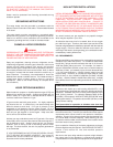
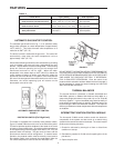
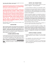
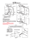
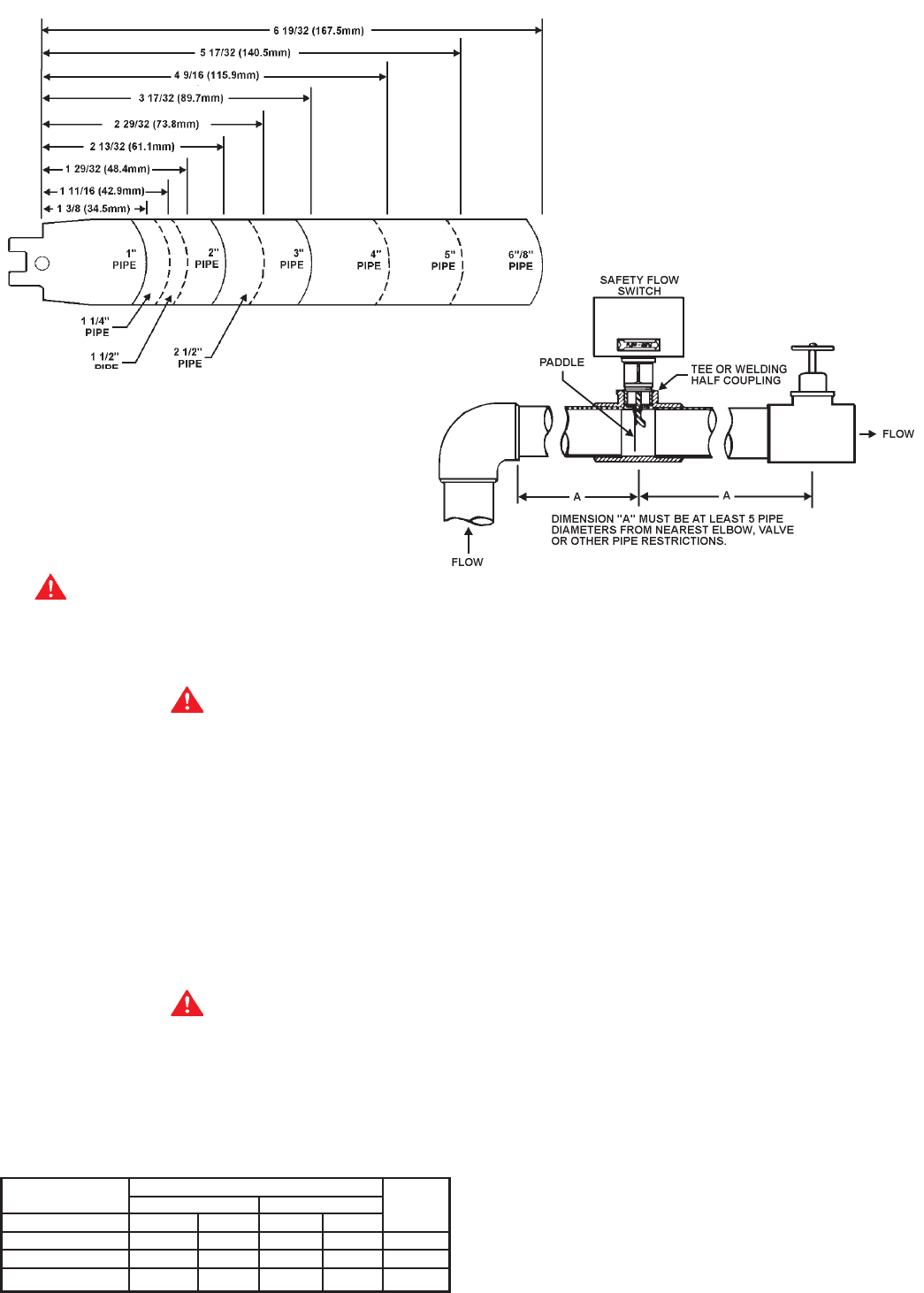
Any part of the paddle must not touch the pipe or any restrictions
in the pipe. Screw the flow switch in position so the flat of the
paddle is at right angles to the flow. The arrow on the side case
must point in the direction of the flow.
The safety flow switch may be field adjusted to obtain higher
minimum flow rates than those shown in Table 5.
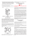
To adjust the flow rate setting:
1. Remove the flow switch cover.
2. For higher flow rate—turn the range adjusting screw clockwise.
3. For lower flow rate—turn the range adjusting screw
counterclockwise.
CAUTION
The switch is factory set at approximately the minimum flow rate,
see Table 5. It must not be set lower than the factory setting as
this may result in the switch failing to return at a
“no flow” condition.
4. Replace the flow switch cover.
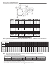
TABLE 5 - SAFETY FLOW SWITCH SETTINGS
Minimum Flow Rate (GPM)
Contacts Close Contacts Close Pkg.
Model GPM LPM GPM LPM No.
HW-120M,160M 0.6 2.3 0.3 1.1 211480
HW-200M 4.2 15.9 2.5 9.5 211480
HW-225M 5.8 22.0 3.7 14.0 211480
The installer is cautioned to follow the manufacturer’s instructions
exactly when inserting this switch into a pipe tee. This is necessary
in order to assure positive action of the switch with water flow.
Once the minimum flow rate (Table 5) through the heater is
reached, the safety flow switch contacts close and consequently,
main burner operation is achieved.
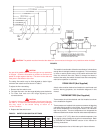
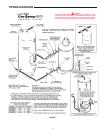
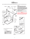
DRAIN VALVE (Not Supplied)
A drain valve must be obtained and installed on each heater and
tank for draining purposes, see installation diagrams in this
manual.
THERMOMETERS (Not Supplied)
Thermometers should be obtained and field installed as shown
in the installation diagrams.
Thermometers are installed in the system as a means of detecting
a possible liming condition in the heater. An increase of 5
0
F over
the normal temperature rise through the heater is an indication
that lime is present. The term “temperature rise” designates the
difference between the heater inlet and outlet water temperatures.
An increase of 5
0
F (3°C) above the recorded temperature rise
may signify a liming condition in the coils or heat exchanger. Refer
to PREVENTIVE MAINTENANCE section of this manual for
deliming instructions.
Record temperature rise at initial start-up for future reference.
CAUTION: The paddle must be trimmed at the dotted arc. It must not touch the pipe or any restrictions when installed.
FIGURE 5