


6
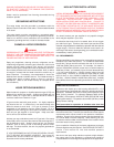
4. Discontinues ignition spark when the pilot flame is established.
The S-8600 control used on propane gas models provides
safety lockout if the pilot fails to ignite within the pilot flame
establishing period. The S-8600 control used on natural gas
models continues trial for ignition until pilot flame is established.
5. After proof-of-pilot flame, opens the main valve.
6. On a power loss, shuts the heater down. When power is
restored it will begin a new ignition cycle.
7. On a loss of flame, shuts off main gas and starts trial for pilot
ignition.
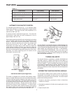
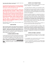
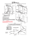
INTERMITTENT IGNITION CONTROL MODULE (I.I.D.)
FIGURE 3
CIRCULATING PUMP
Constant circulating pump operation of the heater voids the
warranty. Constant water flow through the unit will “wash” away
the copper’s natural protective coating. This is called velocity
erosion. This erosion is not as great a problem when intermittent
circulating operation is used per the recommended installation
procedure. Constant circulation of water between the storage
tank and the building is permissible as long as the water does not
constantly flow through the heater.
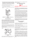
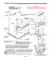
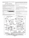
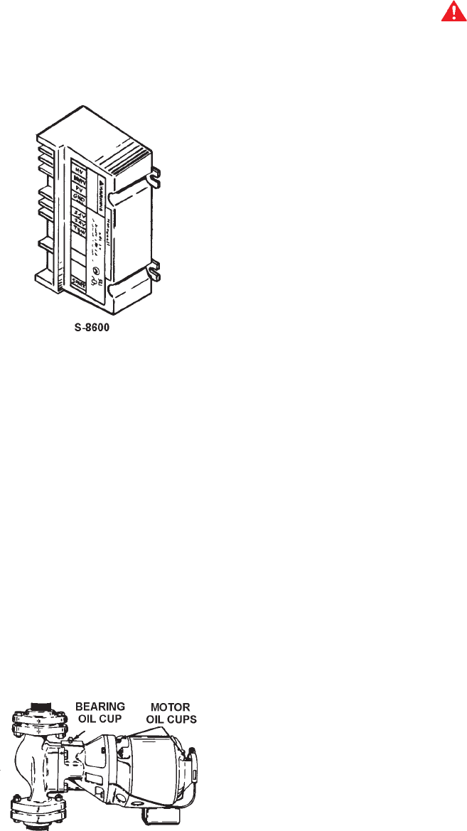
Only all bronze circulators are used with commercial water heaters.
Although circulators are oiled and operated by the manufacturer,
THEY MUST BE OILED AGAIN BEFORE OPERATED. Oil the
three oil cups (2 on the motor, 1 on the pump) as instructed by
manufacturer. See fig. 4.
Thereafter, lubricate the three oil cups at least once every 4
months.
TYPICAL CIRCULATING PUMP
FIGURE 4
Use 2 or 3 teaspoonsful in bearing oil cups, and 10 or 12 drops in
the motor oil cups. Use no. 20 non-detergent motor oil.
Follow the same oiling procedure if a replacement circulator is
installed into the system.
TANK TEMPERATURE CONTROL
(Not Supplied)
DANGER
USE ANTI-SCALD VALVE(S) in the hot water system to reduce
the risks of scalds at points of use such as lavatories, sinks and
bathing facilities.
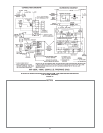
The tank temperature control is located in the lower portion of the
hot water storage tank, see PIPING DIAGRAMS. It is the primary
operating control of the system and regulates the water
temperature in the tank.
The storage tank thermostat should have contact ratings that
exceed the maximum electrical requirements of the system.
Typically, the thermostat should have motor full load and locked
rotor current ratings which exceed the total amount of current
required to drive the pump(s) controlled by the thermostat.
The thermostat should have a temperature range of 100
0
F
(37.7°C) to 180
0
F (82.2°C) or more. The preferred initial setting
for the storage tank thermostat is 120
0
F (48.8°C). However, for
normal use, the thermostat should be adjusted to the lowest setting
which produces an acceptable hot water supply temperature. This
will always give the most energy efficient operation. Do not adjust
the thermostat to achieve a storage temperature of 190
o
F (87.7°C)
or above. This action may cause the automatic gas shutoff control
to activate shutting down the heater.
Intermittent ignition device and circulator start and stop
simultaneously as the tank thermostat contacts open and close.
This basic action, water flowing whenever the burner operates,
must not be altered.
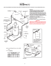
SAFETY FLOW SWITCH
(Not Supplied)
The safety flow switch is a safety device installed at the water
outlet of the unit to prevent main burner operation in the event of
inadequate water flow through the unit.
An accessory package A.O.S. No. 211480 containing a safety
flow switch is available for this application.
This switch may be mounted in a horizontal pipe line or a vertical
pipe line with upward water flow. Do not install the switch where
the water flow is downward.
For proper performance mount the switch in a section of pipe
where there is a straight run of at least 5 pipe diameters on each
side of the flow switch (i.e. do not locate adjacent to valves, elbows,
orifices, etc.).
The flow switch shall be mounted in a standard 1" x 1" x 1" tee for
a 1" pipe application. For larger pipe sizes use a reducing tee in
order to keep the switch as close to the pipe as possible. Install
the flow switch in the branch (top) opening of the reducing tee
and provide adequate paddle length in the flow stream. For
example in a 2" pipe installation use a 2" x 2" x 1" reducing tee.
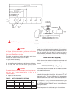
For 1", 2" or 3" pipe use the paddle segments as supplied. For
other pipe sizes (i.e. 1 1/4", 1 1/2", and 2 1/2") trim the paddle to
the proper pipe size, see fig. 5. If a standard tee is used, install a
face or hex bushing in the top opening. The paddle must be
adjusted or trimmed to the size of the pipe in which it will be
installed.