


14
GAS CONNECTIONS
WARNING
THE INLET GAS PRESSURE MUST NOT EXCEED THE VALUE
SPECIFIED BY THE MANUFACTURER ON THE RATING PLATE
(10.5" W.C. - NATURAL GAS, 13.0" W.C. - PROPANE GAS).
EXPOSURE TO HIGHER GAS SUPPLY PRESSURE MAY CAUSE
DAMAGE TO THE GAS VALVE WHICH COULD RESULT IN FIRE
OR EXPLOSION. IF OVERPRESSURE HAS OCCURRED SUCH
AS THROUGH IMPROPER TESTING OF GAS LINES OR
EMERGENCY MALFUNCTION OF THE SUPPLY SYSTEM, THE
GAS VALVE MUST BE CHECKED FOR SAFE OPERATION. MAKE
SURE THAT THE OUTSIDE VENTS ON THE SUPPLY
REGULATORS AND THE SAFETY VENT VALVES ARE
PROTECTED AGAINST BLOCKAGE. THESE ARE PARTS OF
THE GAS SUPPLY SYSTEM, NOT THE HEATER. VENT
BLOCKAGE MAY OCCUR DURING ICE STORMS.
IT IS IMPORTANT TO GUARD AGAINST GAS VALVE FOULING
FROM CONTAMINANTS IN THE GAS WAYS. SUCH FOULING
MAY CAUSE IMPROPER OPERATION, FIRE OR EXPLOSION.
IF COPPER SUPPLY LINES ARE USED THEY MUST BE
INTERNALLY TINNED AND CERTIFIED FOR GAS SERVICE.
BEFORE ATTACHING THE GAS LINE BE SURE THAT ALL GAS
PIPE IS CLEAN ON THE INSIDE.
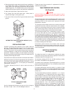
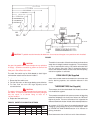
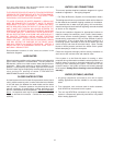
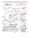
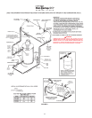
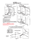
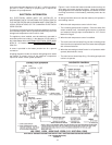
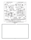
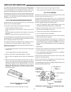
TO TRAP ANY DIRT OR FOREIGN MATERIAL IN THE GAS
SUPPLY LINE, A DIRT LEG (SOMETIMES CALLED SEDIMENT
TRAP OR DRIP LEG), MUST BE INCORPORATED IN THE
PIPING. SEE PIPING DIAGRAMS. THE DIRT LEG MUST BE
READILY ACCESSIBLE AND NOT SUBJECT TO FREEZING
CONDITIONS. INSTALL IN ACCORDANCE WITH
RECOMMENDATIONS OF SERVING GAS SUPPLIERS. IN THE
UNITED STATES REFER TO ANSI Z223.1-1999 OR MOST
RECENT EDITION OF THE NATIONAL FUEL GAS CODE. IN
CANADA, THE CANADIAN INSTALLATION CODE CAN/CGA
B 149 (LATEST EDITION).
To prevent damage, care must be taken not to apply too much
torque when attaching gas supply pipe to gas valve gas inlet.
Fittings and unions in the gas line must be metal to metal type.
Apply joint compounds (pipe dope) sparingly and only to the male
threads of pipe joints. Do not apply compound to the first two
threads. Use compounds resistant to the action of liquefied
petroleum gases.
BEFORE PLACING THE HEATER IN OPERATION, CHECK FOR
GAS LEAKAGE. Use soap and water solution or other material
acceptable for the purpose in locating gas leaks. DO NOT USE
MATCHES, CANDLES, FLAME OR OTHER SOURCES OF
IGNITION FOR THIS PURPOSE.
DISCONNECT THE HEATER AND ITS MANUAL GAS SHUTOFF
VALVE FROM THE GAS SUPPLY PIPING SYSTEM DURING
ANY PRESSURE TESTING OF THAT SYSTEM AT TEST
PRESSURES IN EXCESS OF 1/2 PSIG. THE GAS SUPPLY
LINE MUST BE CAPPED WHEN NOT CONNECTED TO
HEATER.
THE HEATER MUST BE ISOLATED FROM THE GAS SUPPLY
PIPING SYSTEM BY CLOSING ITS MANUAL GAS SHUTOFF
VALVE DURING ANY PRESSURE TESTING OF THE GAS
SUPPLY PIPING SYSTEM AT TEST PRESSURES EQUAL TO
OR LESS THAN 1/2 PSIG (3.44kPa).
CORRECT GAS
MAKE SURE the gas on which the heater will operate is the same
as that specified on the heater model and rating plate. Do not
install the heater if equipped for a different type gas - contact the
heater supplier.
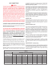
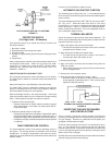
SIZING GAS SUPPLY LINE
The iron pipe or equivalent pipe sizes in Table 6 are derived from
Table C-3 in the NATIONAL FUEL GAS CODE. The pipe sizes
are based on a supply line gas pressure drop of 0.3 inches of
water column from the gas meter to the point of installation of the
heater(s). For natural gas, a heating value of 1050 Btu/ft
3
and a
specific gravity of 0.60 has been assumed. A heating value of
2500 Btu/ft
3
and a specific gravity of 1.53 has been assumed for
L.P. (propane) gas.
Where it is necessary to use an excess number of pipe fittings,
i.e., elbows, tees and valves, in the gas supply line, use pipe at
least one size larger than that recommended in Table 2 to
compensate for the increased pressure drop.
If the service pressure is 4.5 inches W.C. (1.12kPa) (11 inches
(1.74kPa) for L.P. gas) of water column or less, use pipe size
larger than specified in Table 6 to minimize pressure drop in the
line.
GAS METER SIZE - City Gases Only
Be sure that the gas meter has sufficient capacity to supply the
full rated gas input of the heater as well as the requirements of all
other gas fired equipment supplied by the meter. If gas meter is
too small, ask the gas company to install a larger meter having
adequate capacity.
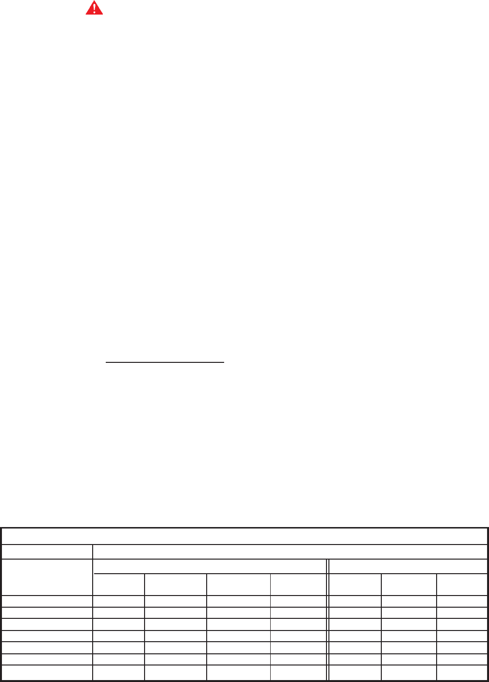
TABLE 6
GAS SUPPLY PIPE SIZES (IN INCHES)
NATURAL GAS (1050 Btu/ft
3
) PROPANE GAS (2500 Btu/ft
3
)
Distance To Heater
From Meter (FT./M) HW-120M HW-160M HW-200M HW-225M HW-120M HW-160M HW-200M
10 (3M) 1/2 3/4 3/4 3/4 1/2 1/2 1/2
30 (9.1M) 3/4 3/4 1 1 1/2 3/4 3/4
50 (15.2M) 3/4 1 1 1 3/4 3/4 1
80 (24.4M) 1 1 1 1/4 1 1/4 3/4 1 1
100 (30.5M) 1 1 1/4 1 1/4 1 1/4 3/4 1 1
150 (45.7M) 1 1 1/4 1 1/4 1 1/4 1 1 1 1/4
200 (61M) 1 1/4 1 1/4 1 1/4 1 1/2 1 1 1/4 1 1/4