26
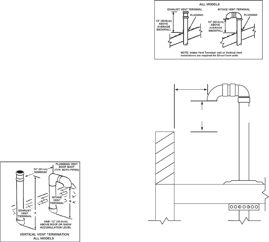
VERTICAL VENT TERMINAL INSTALLATION
WHEN TERMINATING THROUGH A ROOF, THE FOLLOWING
SPECIFICATIONS PERTAINING TO TERMINAL LOCATION
MUST BE FOLLOWED.
1. Proper support must be provided for all pipe protruding through
the roof.
2. The vertical roof terminations should be sealed with a plumbing
roof boot or equivalent ashing.
3. The intake vent termination and the exhaust vent termination
must penetrate the same side of roof.
4. The center line of the intake vent termination and the center
line of the exhaust vent termination must be no closer than 24”
(61cm).
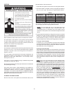
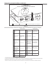
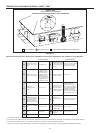
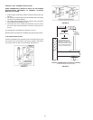
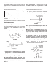
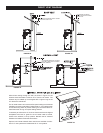
The specications are displayed in Figures 17 and 18.
NOTE: Exhaust vent terminal is installed using the same procedure.
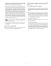
FLAT ROOF INSTALLATION
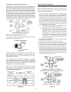
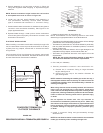
On at roof installations the intake air and the vent terminations must
be a minimum of 24 inches (60 cm) above any parapet, vertical wall
or structure within 10 feet (3 m) horizontally. See gure 19.
FIGURE 17.
FIGURE 18.
INTAKE AIR AND/OR VENT
TERMINATION(S) MUST BE A
MINIMUM OF 24 INCES (60 cm)
ABOVE ANY PARAPET, VERTICAL
WALL OR STRUCTURE WITHIN
10 FEET (3 m) HORIZONTALLY.
VERTICAL TERMINATION(S) FLAT ROOF CLEARANCE
INTAKE AIR AND/OR VENT (EXHAUST)
24 INCHES (60 cm)
MINIMUM HEIGHT ABOVE
IF LESS THAN
10 FEET (3 m)
NOTE:
INTAKE VENT
TERMINATION
SHOWN HERE
FIGURE 19.


