


2
6. Place your motherboard on the brass standoffs.
7. Screw in your motherboard to the standoffs with the provided Philips-head
screws. Your motherboard is now installed.
Front Bezel Connectors
1. Connect the Reset switch (labeled RESET SW) to your motherboard at the RST
connector. The white wire for each connector should be on the ground pin.
2. Power LED (labeled POWER LED) connector is located behind the Reset
connector.
3. Power Switch (labeled POWER SW) connects to the PWR connector on the
motherboard.
4. Hard Drive LED I & II (labeled HDD I, HDD II) connectors. You may use these
LEDs for indicating activity on two different hard drives, or any other indication
your system supports.
Connecting the USB Ports
You will find a single 10-pin connector on a cable attached to the front USB ports.
This is an Intel standard connector, which is keyed so that it can’t be accidentally,
reversed as long as it is connected to a proper Intel standard motherboard header.
Connect the 10-pin connector to your motherboard headers so that the blocked pin
fits over the missing header pin.
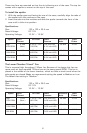
Note: Please check your motherboard manual for your USB header pin layout and
make sure it matches the attached table. If it does not match this Intel standard,
please contact your motherboard manufacturer for an adapter. You may also call
Antec customer support at (800) 22ANTEC (North America) or
+31 (0) 10 462-2060 (Europe) to purchase a USB adapter. This adapter will allow
you to connect the front USB to your motherboard on a pin-by-pin basis.
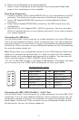
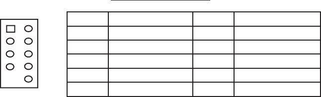
Motherboard Pin Layout
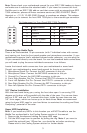
Connecting the IEEE 1394 (FireWire®, i.Link®) Port
You will find a single 10-pin connector on a cable attached to the front IEEE 1394
connection. This is an Intel standard connector, which is keyed so that it can’t be
accidentally reversed as long as it is connected to a proper Intel standard mother-
board header. Connect the 10-pin connector to your motherboard header so that
the blocked pin fits over the missing header pin.
Pin Signal Names Pin Signal Names
1
USB Power 1
2
USB Power 2
3
Negative Signal 1
4
Negative Signal 2
5
Positive Signal 1
6
Positive Signal 2
7
Ground 1
8
Ground 2
9
Key (No Connection)
10
Empty Pin
12
109