


36
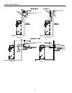
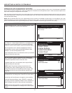
LOW PROFILE TERMINATION INSTALLATION
This water heater is certied for sidewall direct venting with IPEX
System 636 Low Prole Vent Kit. Follow instructions below for proper
installations.
All termination kits must be located and installed in accordance with
local codes or the current editions of the National Fuel Gas Code
(ANSI Z223.1/NFPA 54).
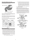
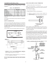
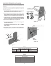
1. Once the proper location has been determined, cut 2 holes in the
wall large enough to accomodate the pipe. Pipe diameters and
distance between hole centers can be found in Table 9.
2. Slide both the intake and exhaust pipes through the holes. Solvent
cement both pipes to the base of the vent termination kit, follow the
solvent cementing procedures outlined in the IPEX System 636
Installation Guide, which is available on the web www.ipexinc.com.
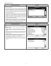
3. To fasten the Base to the wall, use the supplied screws and anchors.
A 3/16” (5mm) hole, 1-3/16” (30mm) deep, will need to be drilled for
the anchors. Locate the anchor hole using the base as a template.
4. Screw the Cap to the Base using the supplied screws.
5. Once the vent termination and pipes are secured, the wall
penetrations will need to be sealed from the interior using a PVC-
compatible sealant material.
6. All vent pipes and air inlets must terminate at the same height to
avoid possibility of severe personal injury, death, or substantial
property damage.
8. Operate heater through 1 heat cycle to ensure combustion-air and
vent pipes are properly connected to concentric vent termination
connections.
Figure: 32
Vent Base
Vent Cap
Air Piping
Vent Piping
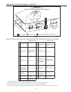
Table 9
Low Prole Termination Kits - Dimensions
AOS Kit
Number
IPEX Part
Number
Description
Pipe Outside
Diameter
Hole Spacing
(ctr to ctr)
327479-000 196984 2” Flush Mount Vent Kit 2.375” 5.6”
327478-000 196985 3” Flush Mount Vent Kit 3.5” 5.6”
Table 10
Each Kit Contains
Qty Item Description
1 Base (two holes)
1 Cap (one hole)
8 Stainless Steek Screws
4 Plastic Anchors
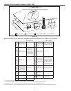
To Boiler Intake
Air Connection
From Boiler Vent
Pipe Connection
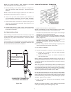
Vent/Air
Termination
12”
Min to
Over-
Hang
12”
Min
Grade or
Snow Line
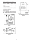
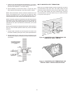
Possible Orientations
12” Min between Edge of Air
Inlet and Adjacent Vent Outlet
Air
Vent/Air
Termination
Vent
Figure: 33
Figure: 34