


35
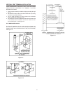
5. Install rain cap and small diameter pipe assembly in Y concentric
tting and large pipe assembly. Ensure small diameter pipe is
bottomed and cemented in Y concentric tting.
6. Secure assembly to structure as shown in “Figure: 28” using
eld-supplied metal strapping or equivalent support material.
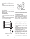
NOTE: Ensure termination location clearance dimensions are as
shown in the diagrams found in “Figure: 28” and Figure 29. When
extending the length of the 4” pipe, the added length beyond 21-1/8”
must be deducted from the maximum equivalent feet of vent pipe.
NOTE: If assembly needs to be extended to allow side wall thickness
requirement, the 2 pipes supplied in the kit may be replaced by
using same diameter, eld-supplied SDR-26 PVC (D2241) pipe. Do
not extend 21 1/8” (53.6 cm) dimension more than 60” (1.5 m). See
“Figure: 24”.
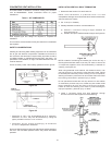
Do not use eld-supplied couplings to extend pipes. Airow restriction
will occur and the heater pressure switch may cause intermittent
operation.
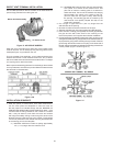
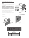
7. Cement heater combustion-air and vent pipes to concentric vent
termination assembly. See Figure 29 for proper pipe attachment.
8. Operate heater through 1 heat cycle to ensure combustion-air and
vent pipes are properly connected to concentric vent termination
connections.
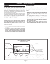
Figure: 29
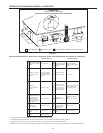
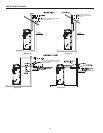
MULTI-CONCENTRIC VENT TERMINATIONS
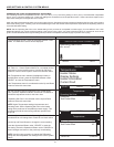
When two or more water heaters are direct vented with concentric
vent terminations near each other, each water heater must be
individually vented. NEVER common vent this water heater. When
two or more water heaters are direct vented using concentric
vent terminations, the water heaters may be vented as shown
in Figure 30 and Figure 31.
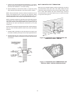
Figure 30: CONCENTRIC VENT TERMINATIONS FOR
HORIZONTAL DIRECT VENTING
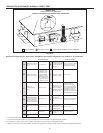
Figure 31: CONCENTRIC VENT TERMINATIONS FOR
VERTICAL DIRECT VENTING THROUGH A ROOF