


24
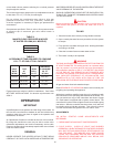
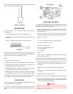
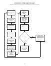
Servicing of the ignitor assembly includes keeping the ignitor free
of lint, scale or any other foreign debris.
FIGURE 11, IGNITOR
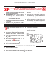
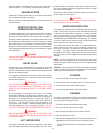
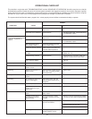
MAIN BURNER
The main burner, fig.12, should display the following
characteristics:
• Cause rapid ignition and carry across entire burner.
• Give reasonably quiet operation during ignition, burning, and
extinction.
• Cause no excessive lifting of flame from burner ports.
FIGURE 12
If the preceding burner characteristics are not evident, check for
accumulation of lint, scale or other foreign debris that restricts or
blocks the air openings to the burner or heater.
NOTE:
1. Remove main burners from unit.
2. Check that burner venturi and ports are free of foreign debris.
3. Clean burners with bristle brush and/or vacuum cleaner - DO
NOT distort burner ports or pilot location.
4. Reinstall burners in unit. Make sure front and rear of burners
are installed correctly in burner support brackets.
5. Check flame inserts. Make sure there is no bending or cracking
and that they are free from lint, scale or any foreign material.
Also check for good flow of combustion and ventilating air to the
unit. Maintain a clear area around the heater at all times.
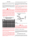
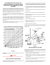
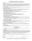
GAS VALVES
Figure 13 shows the type of combination manual gas control valve
and regulator used on these heaters.
If the gas valve becomes defective, repairs should not be
attempted. A new valve should be installed in place of the defective
one.
FIGURE 13
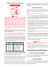
CHECKING THE INPUT
For appliance installation locations with elevations above 2000
feet, refer to HIGH ALTITUDE INSTALLATIONS section of this
manual for input reduction procedure.
1. Attach a pressure gauge or a manometer to the manifold
pressure tap on the gas valve and refer to Table 3, for correct
manifold pressure.
2. Use this formula to “clock” the meter. Be sure that other gas
consuming appliances are not operating during this interval.
3600 X H = Btuh
T
T = Time in seconds to burn one cubic foot of gas.
H = Btu’s per cubic foot of gas.
Btuh = Actual heater input.
Example: (Using BTN-250 heater)
T = 15.1 seconds
H = 1050 Btu
Btuh = ?
36.8 X 1050 = 250,000 Btuh (Compare with the 100T250-
6NOX model and rating.)
Should it be necessary to adjust the gas pressure to the burners
to obtain the full input rate, the steps below should be followed:
3. Remove the regulator adjustment sealing cap, fig. 13, and
adjust the pressure by turning the adjusting screw with a
screwdriver.
Clockwise to increase gas pressure and input rate.
Counterclockwise to decrease gas pressure and input
rate.
4. “Clock” the meter as in step 2 above.
5. Repeat steps 3 and 4 until the specified input rate is achieved.
6. Turn the gas control knob to PILOT. Remove the pressure
gauge and replace the sealing cap and the allen wrench set
screw in the pressure tap opening.
WARNING
UNDER NO CIRCUMSTANCES SHOULD THE GAS INPUT
EXCEED THE INPUT SHOWN ON THE HEATER MODEL AND
RATING PLATE. OVERFIRING COULD RESULT IN DAMAGE
OR SOOTING OF THE HEATER.