


23
WATER TEMPERATURE CONTROL
DANGER
THIS WATER HEATER IS EQUIPPED WITH AN ADJUSTABLE
THERMOSTAT TO CONTROL WATER TEMPERATURE. HOT
WATER TEMPERATURES REQUIRED FOR AUTOMATIC
DISHWASHER AND LAUNDRY USE CAN CAUSE SCALD
BURNS RESULTING IN SERIOUS PERSONAL INJURY AND/
OR DEATH. THE TEMPERATURE AT WHICH INJURY OCCURS
VARIES WITH THE PERSON'S AGE AND TIME OF EXPOSURE.
THE SLOWER RESPONSE TIME OF CHILDREN, AGED OR
DISABLED PERSONS INCREASES THE HAZARDS TO THEM.
NEVER ALLOW SMALL CHILDREN TO USE A HOT WATER TAP,
OR TO DRAW THEIR OWN BATH WATER. NEVER LEAVE A
CHILD OR DISABLED PERSON UNATTENDED IN A BATHTUB
OR SHOWER.
THE WATER HEATER SHOULD BE LOCATED IN AN AREA
WHERE THE GENERAL PUBLIC DOES NOT HAVE ACCESS
TO SET TEMPERATURES.
SETTING THE WATER HEATER TEMPERATURE AT 120°F
(49°C) WILL REDUCE THE RISK OF SCALDS.
Some states or
provinces require settings at specific lower temperatures.
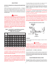
Below you will find listed the approximate time-to-burn relationship
for normal adult skin. Short repeated heating cycles caused by
small hot water uses can cause temperatures at the point of use
to exceed the thermostat setting by up to 20F°. If you experience
this type of use, you should consider using lower temperature
settings to reduce scald hazards.
Temperature Time to Produce 2nd & 3rd
Setting Degree Burns on Adult Skin
180°F (82°C) Nearly instantaneous
170°F (77°C) Nearly instantaneous
160°F (71°C) About 1/2 second
150°F (66°C) About 1-1/2 seconds
140°F (60°C) Less than 5 seconds
130°F (54°C) About 30 seconds
120°F (49°C) More than 5 minutes
Valves for reducing point-of-use temperature by mixing cold and
hot water are available. Also available are inexpensive devices
that attach to faucets to limit hot water temperatures. Contact a
licensed plumber or the local plumbing authority.
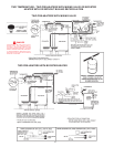
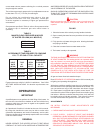
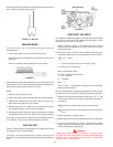
The water temperature is controlled by a thermostat, fig. 2, which
has two sensing elements. One sensor is located near the top of
the tank and the other is near the center. The thermostat is set in
the lowest position before the heater leaves the factory.
The thermostat temperature dial, fig. 2, is accessible by
removing the control cover. The dial is adjustable and may be
set for 120
0
(49°C)
to 180
0
F (82°C) water temperature, but
120
0
F (49°C) is the recommended starting point. It is suggested
the dial be placed on the lowest setting which produces an
acceptable hot water supply. This will always give the most
energy efficient operation. The temperature control has a 4F°
fixed differential.
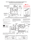
CHECKING VENTING
The following steps shall be followed with each appliance
connected to the venting system placed in operation, while any
other appliances connected to the venting system are not in
operation.
1. Seal any unused openings in the venting system.
2. Inspect the venting system for proper size and horizontal
pitch, as required in the National Fuel Gas Code, ANSI Z223.1
and these instructions. Determine that there is no blockage
or restriction, leakage, corrosion and other deficiencies which
could cause an unsafe condition.
3. So far as is practical, close all building doors and windows
and all doors between the space in which the water heater(s)
connected to the venting system are located and other
spaces of the building. Turn on all appliances not connected
to the venting system. Turn on all exhaust fans, such as
range hoods and bathroom exhausts, so they shall operate
at maximum speed. Close fireplace dampers.
4. Follow the lighting instruction. Place the water heater being
inspected in operation. Adjust thermostat so appliance shall
operate continuously.
5. Test for spillage at the burner level after 5 minutes of main
burner operation.
6. After it has been determined that each BCG3 connected to the
venting system properly vents when tested as outlined above,
return doors, windows, exhaust fans, fireplace dampers and
any other gas burning appliance to their previous conditions
of use.
7. If improper venting is observed during any of the above tests,
the venting system must be corrected.
WARNING
FAILURE TO CORRECT BACK DRAFTS MAY CAUSE AIR
CONTAMINATION AND UNSAFE CONDITIONS.
• If the back draft cannot be corrected by the normal method or
if a suitable draft cannot be obtained, a blower type flue gas
exhauster must be employed to assure proper venting and
correct combustion.
PREVENTIVE MAINTENANCE
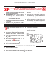
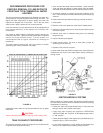
CHECK THE IGNITOR ASSEMBLY
At least once a year, check the ignitor assembly, Fig. 11, and the
main burner, Fig. 12, for proper operation. Refer to the following
ignitor assembly and main burner sections.
IGNITOR ASSEMBLY
For access to ignitor assembly, unfasten two screws to burner
cover and remove. Locate the burner with the ignitor assembly
and remove screw holding burner to manifold. Slide burner out
to access ignitor assembly.