


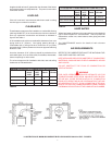
11
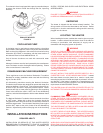
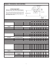
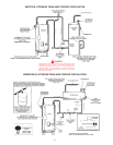
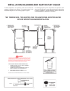
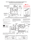
INSTALLATION DIAGRAMS-TOP INLET/OUTLET USAGE
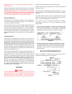
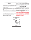
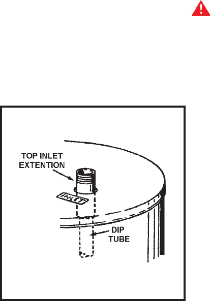
Use of the top inlet water connection requires installation of an
inlet dip tube (refer to figure 8). The tube is supplied in the heater.
Follow caution labels if applying heat to this fitting. Do not allow
pipe dope to contact the plastic tube during installation.
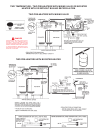
CODE RESTRICTIONS
Use of the top inlet water connection is not permitted on
installations in the state of North Carolina, due to the material of
the tube (Polypropylene). Where such code restrictions exist,
use only lower inlet tank connection. This may also require a
heat trap - check local codes. The “Top Outlet” connection may
still be used on these applications. Plug or cap all unused
openings in the tank before filling with water.
DANGER
TEMPERATURE SETTING SHOULD NOT EXCEED SAFE USE
TEMPERATURE AT FIXTURES. SEE WATER TEMPERATURE
CONTROL WARNING ON PAGE 25. IF HIGHER PREHEAT
TEMPERATURES ARE NECESSARY TO OBTAIN ADEQUATE
BOOSTER OUTPUT, ADD AN ANTI-SCALD VALVE FOR HOT
WATER SUPPLIED TO FIXTURES.
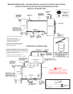
GENERAL
The type, size and location of the relief valves must be in
accordance with local codes. The locations of the relief valves
shown in the installation diagrams are typical. The heater has a
factory installed high temperature limit switch and temperature
and pressure relief valve.
Cold water lines to heater should be installed as shown in order
to minimize gravity circulation of hot water to building cold water
lines.
A listed temperature and pressure relief valve of adequate capacity
is installed on the heater. The locations shown in the installation
diagrams on the following pages are typical.
The discharge opening of the temperature and pressure relief
valve, located in front of the heater must be piped to an open
drain and should not be subject to freezing temperatures.
Install in accordance with all local codes.
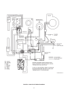
TUBE INLET INSTALLATION
FIGURE 8