


21
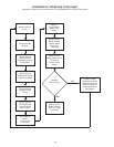
SEQUENCE OF OPERATION
The following information will describe the Sequence of Operation
for this appliance.
1. Switch power on to unit.
2. Thermostat calls for heat.
3. Ignition Control Board performs diagnostic check on system
components.
4. On completion of diagnostics check, the Ignition Control Board
sends signal to Exhaust Inducer.
5. Exhaust Inducer begins drawing air through appliance closing
the Prover Switch.
6. On completion of Prover Switch engagement, the Ignition
Control Board begins the ignition cycle.
7. The Ignition Control Board provides power to the Silicon Nitride
Ignitor.
8. The Silicon Nitride Ignitor heats up for approximately 17 to 20
seconds.
9. At the end of Silicon Nitride Ignitor’s warm-up, the Ignition
Control Board opens the Gas Valve.
10.From the time the Gas Valve opens, the Ignition Control Board
waits 3 seconds and then shuts off power to the Silicon Nitride
Ignitor.
11.From the time the Silicon Nitride Ignitor’s power is shut off, the
Ignition Control Board waits 3 more seconds to monitor the
Flame Sensor.
12.If the Flame Sensor does not detect a strong enough flame,
the Ignition Control Board shuts off the Gas Valve and allows
the Exhaust Inducer to purge the unit for 20 seconds. At that
time, the Ignition Control Board restarts with step 7. It will try
and ignite the main burners 2 more times. If the unit does not
light, the Ignition Control Board will wait one hour and then
restart at step 3. This cycle will continue until the unit lights or
the power is shutoff to the unit.
13.If the Flame Sensor detects a strong flame, the Ignition Control
Board will allow the unit to operate until the thermostat is
satisfied.
14.Once the unit is satisfied, the Ignition Control Board will shut
off the Gas Valve and the unit will be in standby mode until
another call for heat is initiated by the thermostat.
See the flow chart on page 31 for more information.