


9
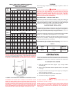
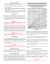
TABLE 4. GAS SUPPLY LINE SIZES (IN INCHES)*
MAXIMUM CAPACITY OF PIPE IN
CUBIC FEET PER HOUR
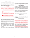
BEFORE PLACING THE HEATER IN OPERATION, CHECK FOR GAS
LEAKAGE. Use soap and water solution or other material acceptable for
the purpose in locating the leaks. DO NOT USE MATCHES, CANDLES,
FLAME OR OTHER SOURCES OF IGNITION FOR THIS PURPOSE.
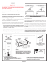
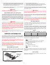
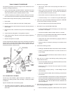
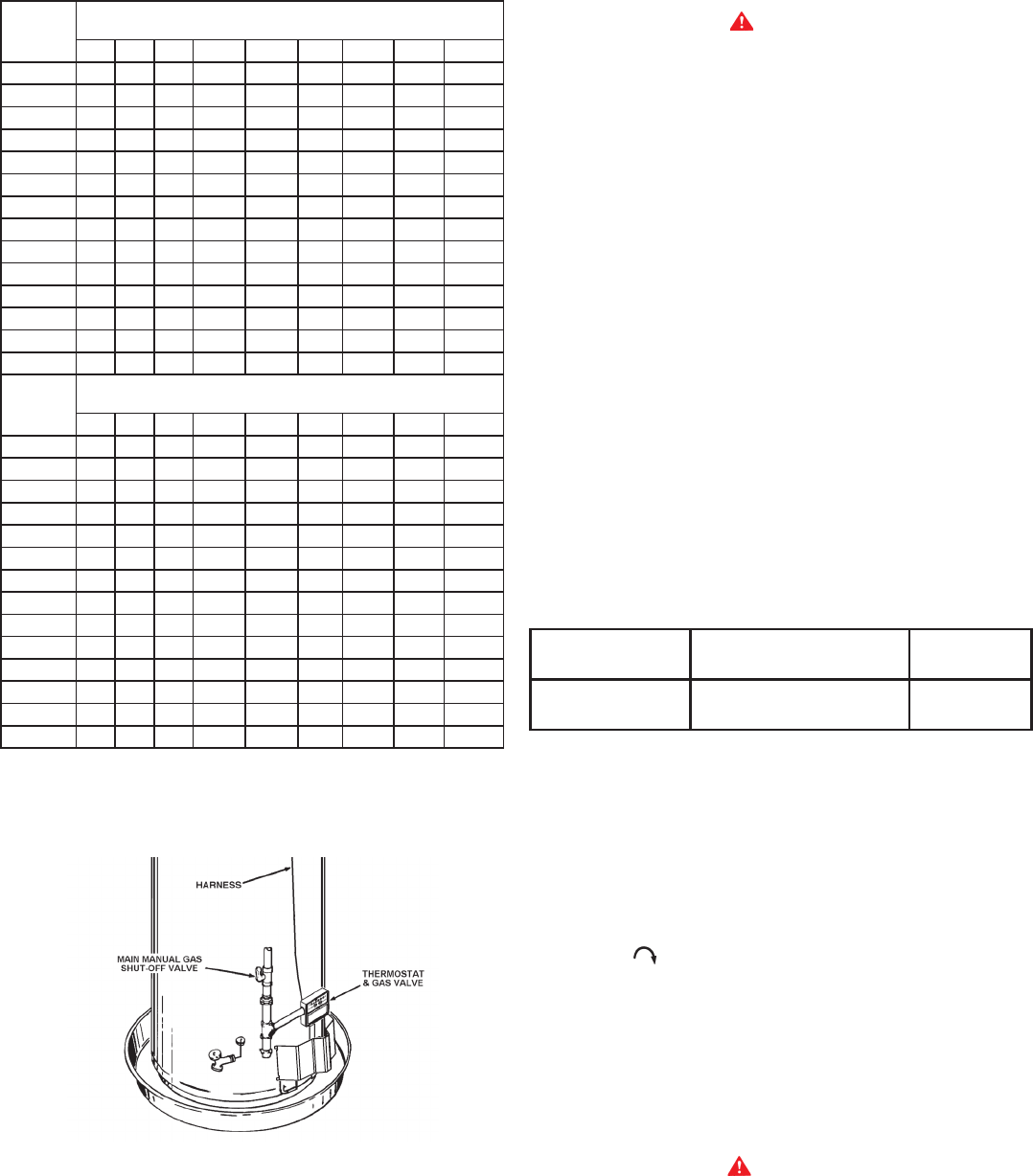
FIGURE 5.
GAS PIPING AND SEDIMENT TRAP INSTALLATION
DISCONNECT THE HEATER AND ITS MANUAL GAS SHUTOFF VALVE
FROM THE GAS SUPPLY PIPING SYSTEM DURING ANY SUPPLY
PRESSURE TESTING EXCEEDING 1/2 PSIG (3.45 kPa). GAS SUPPLY LINE
MUST BE CAPPED WHEN DISCONNECTED FROM THE HEATER FOR TEST
PRESSURES OF 1/2 PSIG (3.45 kPa) OR LESS. THE APPLIANCE NEED
NOT BE DISCONNECTED, BUT MUST BE ISOLATED FROM THE SUPPLY
PRESSURE TEST BY CLOSING THE MANUAL GAS SHUTOFF VALVE.
PURGING
Gas line purging is required with new piping or systems in which air
has entered.
CAUTION
PURGING SHOULD BE PERFORMED BY PERSONS EXPERIENCED
IN THIS TYPE GAS SERVICE. TO AVOID RISK OF FIRE OR
EXPLOSION, PURGE DISCHARGE MUST NOT ENTER CONFINED
AREAS OR SPACES WHERE IGNITION CAN OCCUR. THE AREA
MUST BE WELL VENTILATED AND ALL SOURCES OF IGNITION
MUST BE INACTIVATED OR REMOVED.
GAS METER SIZE — NATURAL GASES ONLY
Be sure the gas meter has sufcient capacity to supply the full rated gas
input of the water heater as well as the requirements of all other gas red
equipment supplied by the meter. If gas meter is too small, ask the gas
company to install a larger meter having adequate capacity.
GAS PRESSURE REGULATOR
The gas pressure regulator is built into the gas valve and is equipped to
operate on the gas specied on model and rating plate. The regulator is
factory adjusted to deliver gas to burner at correct water column pressure
allowing for a nominal pressure drop through the controls.
The minimum gas supply pressure for input adjustment must not be less
than 6" w.c. (1.49 kPa) for natural gas and 11" w.c. (2.73 kPa).
Do not subject the combination gas valve to inlet gas pressures of more
than 14.0" w.c. (3.48 kPa) - natural gas. A service regulator is necessary
if higher gas pressures are encountered.
Gas pressure specied in Table 5, refer to ow pressure taken at pressure
tap of automatic gas valve while heater is operating.
TABLE 5.
Type of
Gas Input
Manifold
Pressure
Natural
75,100 Btu/hr
22 KW/hr
4.0 in. W.C.
1.12 kPa
OPERATION
It is recommended that a qualied person perform the initial ring of the
heater. At this time the user should not hesitate to ask the individual any
questions which he may have in regard to the operation and maintenance
of the unit.
TO OPERATE THE HEATER
1. Close the heater drain valve (Figure 1) by turning handle
clockwise
.
2. Open a nearby hot water faucet to permit the air in the system
to escape.
3. Fully open the cold water inlet pipe valve (Figure 1) allowing the
heater and piping to be lled.
4. Close the hot water faucet as water starts to ow.
5. The heater is ready to be operated.
WARNING
DO NOT ATTEMPT TO OPERATE WATER HEATER WITH COLD
WATER INLET VALVE CLOSED.
NEVER OPERATE THE HEATER WITHOUT FIRST BEING CERTAIN
IT IS FILLED WITH WATER AND A TEMPERATURE AND PRESSURE
RELIEF VALVE IS INSTALLED IN THE RELIEF VALVE OPENING OF
THE HEATER.
LENGTH
IN
FEET
NORMAL IRON PIPE SIZES (INCHES)
INPUT IN THOUSANDS BTU/HR
1/2" 3/4" 1" 1 1/4" 1 1/2" 2" 2 1/2" 3" 4"
10 175 360 680 1400 2100 3960 6300 11000 230000
20 120 250 485 950 1460 2750 4360 7700 15800
30 97 200 375 770 1180 2200 3520 6250 12800
40 82 170 320 660 990 1900 3000 5300 10900
50 73 151 285 580 900 1680 2650 4750 9700
60 66 138 260 530 810 1520 2400 4300 8800
70 61 125 240 490 750 1400 2250 3900 8100
80 57 118 220 460 690 1300 2050 3700 7500
90 53 110 205 430 650 1220 1950 3450 7200
100 50 103 195 400 620 1150 1850 3250 6700
125 44 93 175 360 550 1020 1650 2950 6000
150 40 84 160 325 500 950 1500 2650 5500
175 37 77 145 300 460 850 1370 2450 5000
200 35 72 135 280 430 800 1280 2280 4600
LENGTH
IN
METERS
NORMAL IRON PIPE SIZES (INCHES)
INPUT IN KW
1/2" 3/4" 1" 1 1/4" 1 1/2" 2" 2 1/2" 3" 4"
3.0 51 105 199 410 615 1160 1845 3221 6735
6.1 35 73 142 278 428 805 1277 2255 4626
9.1 28 59 110 225 346 644 1031 1830 3748
12.2 24 50 94 193 290 556 878 1552 3192
15.2 21 44 83 170 264 492 776 1391 2840
18.3 19 40 76 155 237 445 703 1259 2577
21.3 18 37 70 143 220 410 659 1142 2372
24.4 17 35 64 165 202 381 600 1083 2196
27.4 16 32 60 126 190 357 571 1010 2108
30.5 15 30 57 117 182 337 542 952 1962
38.1 13 27 51 105 161 299 483 864 1757
45.7 12 25 47 95 146 278 439 776 1610
53.3 11 23 42 88 135 249 401 717 1464
61.0 10 21 40 82 126 234 375 688 1347