


19
TROUBLESHOOTING GUIDELINES
TROUBLE SHOOTING
Please check guidelines below. For your safety, water heater service should be performed only by a qualied service technician.
Read the GENERAL SAFETY INFORMATION section rst.
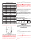
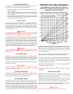
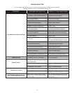
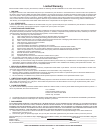
INTELLI-VENT TROUBLESHOOTING CHART - USER CONTROL
PROBLE
MS
OLUTION
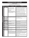
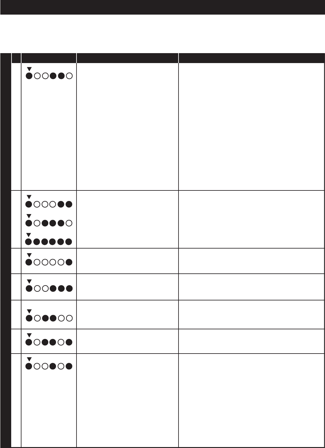
Ignition/flame failure.
6
The water heater has reached the
maximum number of retries and is
currently lockedout for one hour.
Cycle the power to the water heater
off and on to reset.
Service Note:
Theresistance(ohms) of a hot surface
ignitor will increaseovertime. If the
resistanceatroom temperatureis near
18.8 ohms - consider replacing the ignitor
as a preventative measure.
Self diagnostic tests have found a problem 1. Turn the power off for 10-20 seconds then on again to
7with the gas valve driver circuit, internalclear these error codes.
microprocessor, or other internal circuits.
2. If any of these error codes persist or cannot be cleared-
replace the Intelli-Vent™ control.
8
9
Flame signal has been sensed out of 1. Turn the power off for 10-20 seconds and then on again
10 proper sequence. to clear this error code.
2. Replace the Intelli-Vent™ control if this error code persists.
Water temperature in the tank has 1. Turn the power off for 10-20 seconds then on again
11 exceeded 195°F(91°C) and has to clear this error code.
activated the ECO.
2. Replace the Intelli-Vent™ if the error code persists.
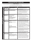
The self diagnostic check detected one
12
13
14
or both of the temperature adjust buttons
are stuck.
The self diagnostic test has detected the
watertemperature sensor (thermistor)is
either open or shorted.
2. Replace the Intelli-Vent™ control if this error code persist.
# LED STATUS
WATERHEATERCONTROL
B C D E F
B C D E F
B C D E F
B C D E F
B C D E F
B C D E F
B C D E F
B C D E F
B C D E F
1. Press and release temperature adjust buttons. If above
action does not clear error, control will continue to regulate
water temperature at last setting. However, settings will no
longer be adjustable - the control should be replaced.
1. Turn power off for 10-20 seconds then on again to
clear this error code.
4. Ensure the flame sensor is clean - use ultra fine steel
wool or Scotch-Brite™ pad to clean flame sensor.
5. Ensure the hot surface ignitor is positioned to provide
consistent ignition.
6. Check for any cracks in ignitor assembly ceramic
insulators - replace ignitor assembly if damaged.
7. Check resistance of ignitor at room temperature (77ºF)
(25°C) at the plug end. Replace ignitor if resistance is
not within 11.5 and 18.8 ohms at room temperature.
8. Ensure correct size of vent pipe (2”, 3”, 4”) was used per
installation manual for vent length. Using larger pipe than required
may cause excessive air turbulance in combustion chamber.
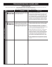
1. Turn off power to the water heater.
2. Insure black resistor wire is not cut, missing, and is installed
between pins 3 & 4 of ignitor assembly plug. Replace ignitor
assembly if damaged or defective.
3. Unplug ignitor assembly plug from control. Check resistance
of black resistor wire between pins 3 & 4 with an ohm meter.
3.1 If reading taken is less than 2000 (5000 for date code 0617
through 0709) or more than 1.7 million ohms, replace ignitor
assembly. 3.2 If reading taken is between 2000 (5000 for date
code 0617 through 0709) and 1.7 million ohms, replace
Intelli- Vent™ control.
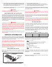
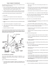
Service Note: Raised ridges on ignitor assembly plug identify
#1, #2, and #3 pins. The four-digit date code can be found on
side of the controller.
Self-diagnostic test found a problem with black
resistor wire on the ignitor assembly plug; resistor
wire is open or shorted.
Service Note:
To perform this test ohm meter
used must be capable of reading up to 2,000,000
ohms. Unless ohm meter used has an auto-range
feature resistance should be checked twice. First
reading will be taken using an ohms scale above
1,700,000 ohms. Second reading is taken using
ohms scale just above 2,000 or 5,000 ohms.
2.
Low supply voltage - should be 115 -125 VAC.
3. Ensure flame sensor is making good contact with burner
flame, ensure flame is steady see #8 below.
1. Gas supply
is turned off-pressure too low. Ensure supply
and
manifold
gas pressures are within requirements in installation
manual. Manifold gas pressure is non-adjustable if pressure is
off by more than
0.3” W.C. (75 Pa)
replace Intelli-Vent™ control.