


18
TROUBLESHOOTING GUIDELINES
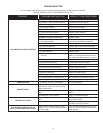
TROUBLE SHOOTING
Please check guidelines below. For your safety, water heater service should be performed only by a qualied service technician.
Read the GENERAL SAFETY INFORMATION section rst.
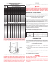
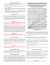
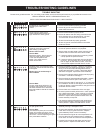
INTELLI-VENT TROUBLESHOOTING CHART - USER CONTROL
PROBLEM
SOLUTION
Inadequate or no earth ground 1. Ensure the wall outlet is properly grounded.
1 sensed by the Intelli-Vent™
control. 2. Ensure all ground connections/wires on the
water heater are secure.
Power supply to Intelli-Vent™ 1. Ensure the wall outlet is properly wired.
2 control has reversed polarity or a
high resistance to earth ground. 2. Ensure all internal 120 VAC wiring connections and
wiring harness have no reversed wires. 120 VAC
“hot” wire must connect to the on/off switch.
3. Ensure the wall outlet is properly grounded.
4. Ensure all ground connections/wires on the water
heater are secure.
Pressure switch circuit remaining 1. Ensure air pressure switch circuit wiring is correct
3 closed for more than 5 seconds and the air pressure switch is not jumpered.
after heating cycle begins.
Blower does not start. 2. Secure power to water heater, check continuity of air
pressure switch contacts with wires disconnected.
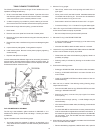
Service Note:
Disconnect power - disconnect one A If pressure switch contacts show continuity (closed
wire from the air pressure switch circuit) replace the pressure switch.
or the vent temperature limit
switch. Turn power back on - B If pressure switch contacts are open and all wiring
blower should start. is correct - turn the power off for 10-20 seconds
then on again to clear the error code - if the error
code persists replace the Intelli-Vent™ control.
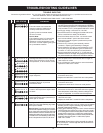
Pressure switch circuit remains open 1. Ensure the blower is running - check for 120 VAC to
4 longer than 5 seconds after the blower the blower when the heating cycle begins, check the
is energized. wiring. If the control does not energize the blower -
replace the Intelli-Vent™ control. If the blower fails to
Blower may run continuously in start when energized - replace the blower assembly.
this condition.
2. Ensure the air pressure switch sensing tube is properly
connected - not kinked or damaged.
3. Check continuity of vent temperature limit switch - replace
switch if contacts remain open under 160ºF (71°C).
4. Ensure the correct size of vent pipe (2”, 3”, 4”) was used
Service Note: per installation manual for vent length. Ensure maximum
To learn more about performing Air number of elbows or equivalent feet of vent pipe has not
Pressure Switch tests visit our web exceeded maximum limits.
site www.hotwater.com to download
technical bulletin A-023-06 Air Pressure 5. Ensure there are no obstructions in the vent pipe.
Switches.
6. Check air pressure switch performance - check pressure
with a digital manometer - check continuity of contacts.
(see service note in left column) If the switch proves
defective - replace the air pressure switch and or the
blower assembly as required.
7. If air pressure switch performance test results prove
the air pressure switch is working properly and error
code 4 persists - replace the Intelli-Vent™ control.
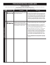
The Intelli-Vent™ control has detected 1. Check wiring to the hot surface ignitor - replace ignitor
5 an open ignitor circuit. assembly if wiring is damaged or worn.
Service Note: 2. Check ignitor assembly plug and the socket on the
The resistance (ohms) of a hot surface Intelli-Vent™ body for good connection. Replace
ignitor will increase over time. If the ignitor assembly and/or control if necessary.
resistance at room temperature is near
18.8 ohms - consider replacing the ignitor 3. Check resistance of ignitor at room temperature 77ºF
as a preventative measure. (25°C) at the plug end. Replace ignitor if resistance
is not within 11.5 and 18.8 ohms at room temperature.
4. If results from the above tests were good and error
code 5 persists - replace the Intelli-Vent™ control.
B C D E F
# LED STATUS
WATER HEATER CONTROL
B C D E F
B C D E F
B C D E F
B C D E F