


6
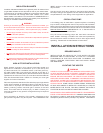
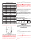
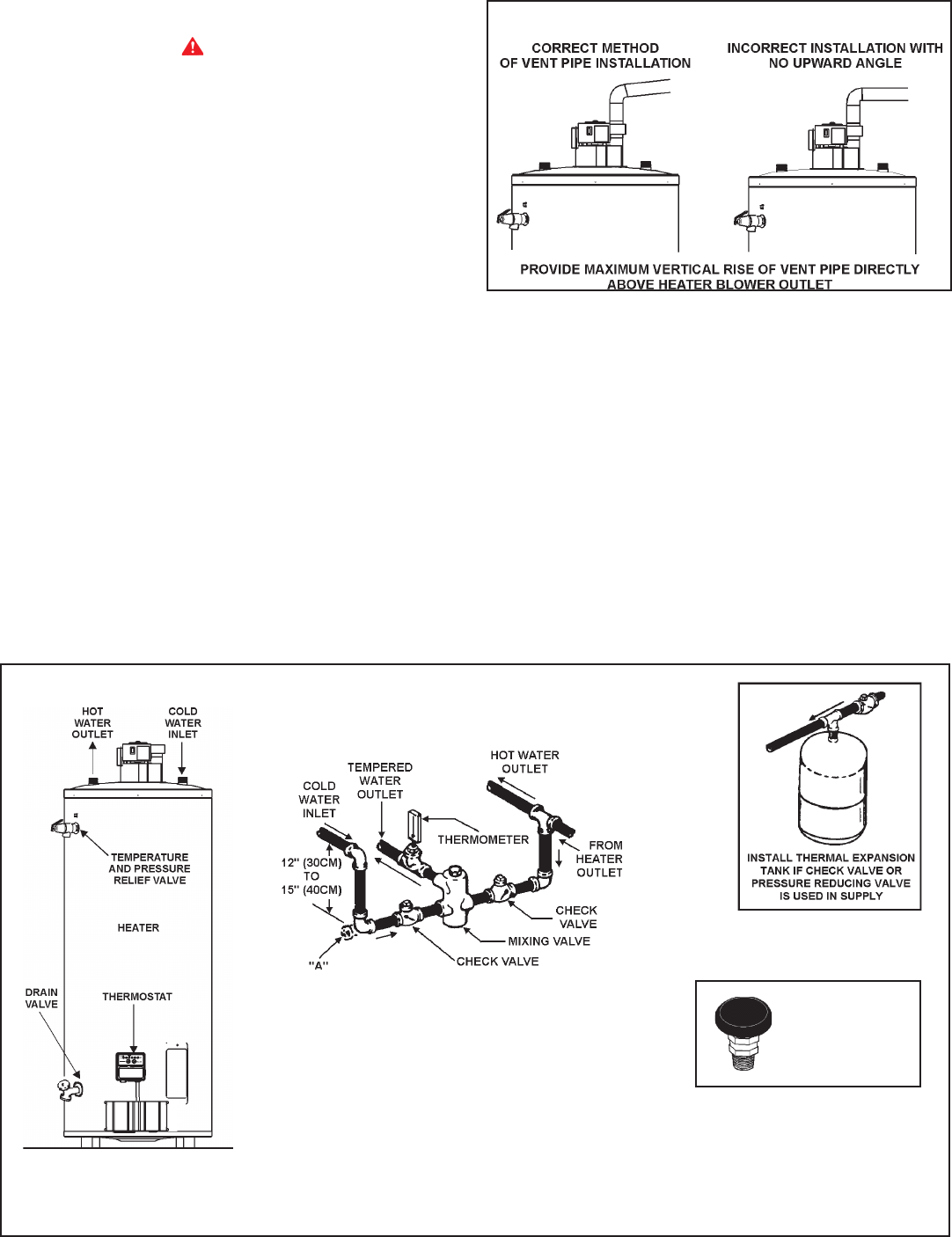
CAUTION: IF BUILDING COLD WATER SUPPLY HAS A BACK-FLOW
PREVENTER, CHECK VALVE OR WATER METER WITH CHECK
VALVE, PROVISIONS FOR THERMAL EXPANSION OF WATER IN
THE HOT WATER SYSTEM MUST BE PROVIDED.
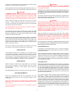
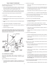
FIGURE 3.
CIRCULATING RETURN LINE CONNECTIONS
TEMPERED WATER LOOP, IF USED, CONNECT TO POINT "A".
STORED TEMPERATURE WATER LOOP, IF USED, CONNECT TO
COLD WATER INLET
WARNING
TEMPERATURE SETTING SHOULD NOT EXCEED SAFE
USE TEMPERATURE AT FIXTURES. SEE TEMPERATURE
REGULATION ON PAGE 11. IF HIGHER PREHEAT
TEMPERATURES ARE NECESSARY TO OBTAIN
ADEQUATE BOOSTER OUTPUT, ADD AN ANTI-SCALD
VALVE FOR HOT WATER SUPPLIED TO FIXTURES.
SINGLE TEMPERATURE
VENTING
WARNING
THE INSTRUCTIONS IN THIS SECTION ON VENTING MUST BE
FOLLOWED TO AVOID CHOKED COMBUSTION OR RECIRCULATION
OF FLUE GASES. SUCH CONDITIONS CAUSE SOOTING OR RISKS
OF FIRE AND ASPHYXIATION.
This water heater must be protected from freezing downdrafts.
Remove all soot or other obstructions from the chimney that will retard
a free draft.
Type B venting is recommended with these water heaters.
This water heater must be vented in compliance with all local codes, the
current edition of the National Fuel Gas Code, ANSI Z223.1/NFPA 54,
and with the Category I Venting Tables.
In Canada, venting shall conform to the requirements of the current
edition of the CAN/CSA B149.1-00 installation code.
If any part of the vent system are exposed to ambient temperatures below
35 degrees F (2 degrees C) it must be insulated to prevent condensation.
• Do not connect the heater to a common vent or chimney with solid
fuel burning equipment. This practice is prohibited by many local
building codes as is the practice of venting gas red equipment to
the duct work of ventilation systems.
• Where a separate vent connection is not available and the vent
pipe from the heater must be connected to a common vent with an
oil burning furnace, the vent pipe should enter the smaller common
vent or chimney at a point above the large vent pipe.
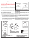
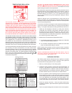
FIGURE 2.
VENT CONNECTION
Vent connections must be made to an adequate stack or chimney. Size
and install proper size vent pipe. Do not reduce pipe size to less than
that of the blower outlet.
Horizontal runs of vent pipe must have a minimum upward slope toward
the chimney of 1/4 inch per foot (2cm per meter). Dampers or other
obstructions must not be installed in between the heater and the blower.
Be sure that the vent pipe does not extend beyond the inside wall of
the chimney.
Where a continuous or intermittent back draft is found to exist, the
cause must be determined and corrected. A special vent cap may be
required. If the back draft cannot be corrected by the normal methods or
if a suitable draft cannot be obtained, a blower type ue gas exhauster
must be employed to assure proper venting and correct combustion.
MIXING VALVE APPLICATION FOR TWO TEMPERATURE WATER
VACUUM RELIEF
VALVE
*INSTALL PER
LOCAL CODES.