


5
LOCATING THE HEATER
WARNING
THERE IS A RISK IN USING FUEL BURNING APPLIANCES SUCH AS
GAS WATER HEATERS IN ROOMS, GARAGES OR OTHER AREAS
WHERE GASOLINE, OTHER FLAMMABLE LIQUIDS OR ENGINE
DRIVEN EQUIPMENT OR VEHICLES ARE STORED, OPERATED OR
REPAIRED. FLAMMABLE VAPORS ARE HEAVY AND TRAVEL ALONG
THE FLOOR AND MAY BE IGNITED BY THE HEATER’S IGNITER OR
MAIN BURNER FLAMES CAUSING FIRE OR EXPLOSION. SOME LOCAL
CODES PERMIT OPERATION OF GAS APPLIANCES IF INSTALLED 18
INCHES (46 cm) OR MORE ABOVE THE FLOOR. THIS MAY REDUCE
THE RISK IF LOCATION IN SUCH AN AREA CANNOT BE AVOIDED.
THE HEATER SHALL BE LOCATED OR PROTECTED SO IT IS NOT
SUBJECT TO PHYSICAL DAMAGE BY A MOVING VEHICLE.
DO NOT LOCATE THE HEATER WHERE NOISE FROM THE EXHAUST
OR INTAKE WILL BE OBJECTIONABLE. THIS INCLUDES LOCATIONS
CLOSE TO OR ACROSS FROM WINDOWS AND DOORS. AVOID
ANCHORING THE VENT AND INTAKE PIPES DIRECTLY TO FRAMED
WALLS, FLOORS OF CEILINGS UNLESS RUBBER ISOLATION PIPE
HANGERS ARE USED. THIS PREVENTS ANY VIBRATIONS FROM
BEING TRANSMITTED INTO THE LIVING SPACES.
WARNING
FLAMMABLE ITEMS, PRESSURIZED CONTAINERS OR ANY OTHER
POTENTIAL FIRE HAZARDOUS ARTICLES MUST NEVER BE PLACED ON
OR ADJACENT TO THE HEATER. OPEN CONTAINERS OF FLAMMABLE
MATERIAL SHOULD NOT BE STORED OR USED IN THE SAME ROOM
WITH THE HEATER.
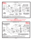
When installing the heater, consideration must be given to proper location.
Location selected should be as close to the intake and exhaust termination
points as practicable, with adequate air supply and as centralized with the
piping system as possible.
THE HEATER MUST NOT BE LOCATED IN AN AREA WHERE IT WILL BE
SUBJECT TO FREEZING.
LOCATE IT NEAR A FLOOR DRAIN. THE HEATER SHOULD BE LOCATED
IN AN AREA WHERE LEAKAGE FROM THE HEATER OR CONNECTIONS
WILL NOT RESULT IN DAMAGE TO THE ADJACENT AREA OR TO LOWER
FLOORS OF THE STRUCTURE.
When such locations cannot be avoided, it is recommended that a suitable
drain pan, adequately drained, be installed under the appliance.
Water heater life depends upon water quality, water pressure and the
environment in which the water heater is installed. Water heaters are
sometimes installed in locations where leakage may result in property
damage, even with the use of a drain pan piped to a drain. However,
unanticipated damage can be reduced or prevented by a leak detector or
water shut-off device used in conjunction with a piped drain pan. These
devices are available from some plumbing supply wholesalers and retailers,
and detect and react to leakage in various ways:
• Sensors mounted in the drain pan that trigger an alarm or turn off the
incoming water to the water heater when leakage is detected.
• Sensors mounted in the drain pan that turn off the water supply to the entire
home when water is detected in the drain pan.
• Water supply shut-off devices that activate based on the water pressure
differential between the cold water and hot water pipes connected to the
water heater.
• Devices that will turn off the gas supply to a gas water heater while at the
same time shutting off its water supply.
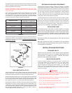
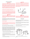
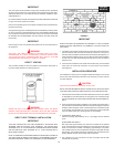
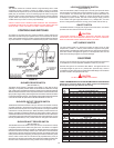
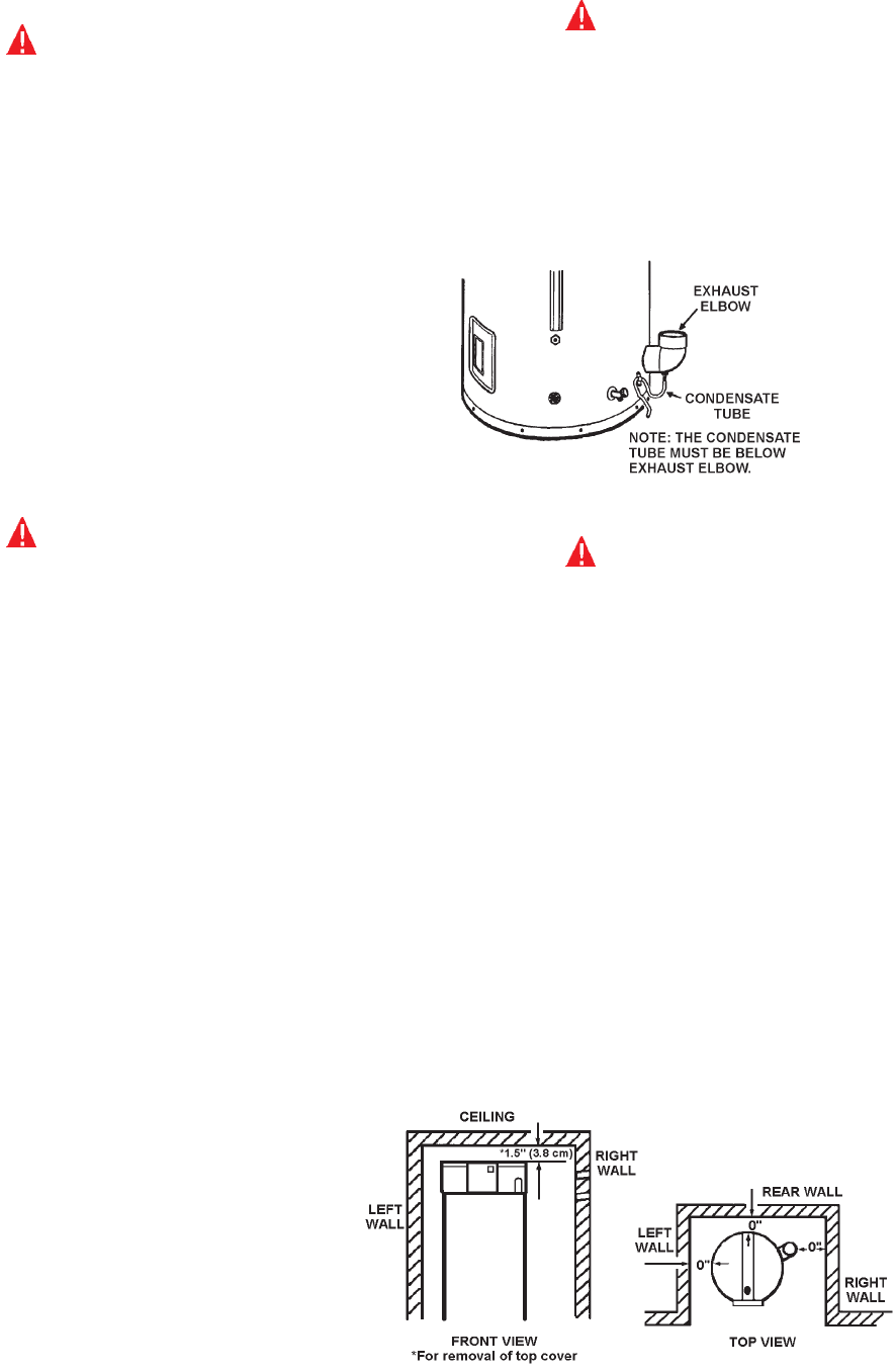
WARNING
THIS WATER HEATER IS A CONDENSING UNIT AND REQUIRES A DRAIN
TO BE LOCATED IN CLOSE PROXIMITY TO ALLOW THE CONDENSATE
TO DRAIN SAFELY. THE CONDENSATE DRAINS FROM THE UNIT AT
THE EXHAUST ELBOW LOCATED AT THE BOTTOM OF THE UNIT. NOTE:
IT IS IMPORTANT THAT THE CONDENSATE HOSE NOT BE ELEVATED
ABOVE THE EXHAUST ELBOW (SEE FIGURE 3). THE CONDENSATE
BUILD-UP WILL BLOCK THE EXHAUST OUTLET, WHICH WILL CAUSE
IMPROPER OPERATION.
FIGURE 3.
WARNING
DO NOT USE THIS APPLIANCE IF ANY PART HAS BEEN UNDER WATER.
IMMEDIATELY CALL A QUALIFIED SERVICE TECHNICIAN TO INSPECT
THE APPLIANCE AND TO REPLACE ANY PART OF THE CONTROL
SYSTEM AND ANY GAS CONTROL WHICH HAS BEEN UNDER WATER.
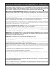
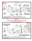
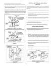
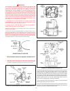
CLEARANCES
These heaters are approved for installation on combustible ooring in an
alcove when the minimum clearances from any combustion construction are
followed as indicated in Figure 4.
In all installations the minimum combustible clearances from any vent piping
shall be 0". Vent piping passing through a combustible wall or ceiling must
be a continuous run (no joints).
A service clearance of 24" (61 cm) should be maintained from serviceable
parts such as relief valves, ue bafes, ue damper devices, thermostats,
cleanout openings or drain valves.
Always disconnect electrical power before servicing the unit.
FIGURE 4.
*ILLUSTRATION OF MINIMUM COMBUSTIBLE CLEARANCES IN AN
ALCOVE.