


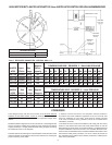
10
IMPORTANT
The vent system must terminate so that proper clearances are maintained
as cited in local codes or the current editions of the National Fuel Gas Code,
ANSI Z223.1/NFPA 54 or the Natural Gas and Propane Installation Code,
CAN/CSA-B149.1.
Do not terminate the exhaust vent terminal over public area where condensate
or vapor can cause nuisance or hazard.
Plan the vent system layout so that proper clearances are maintained from
plumbing and wiring.
Vent pipes serving power vented appliances are classied by building codes
as "vent connectors". Required clearances from combustible materials must
be provided in accordance with information in this manual under LOCATION
OF HEATER and CLEARANCES, and with National Fuel Gas Code and
local Codes.
IMPORTANT
Plan the layout of the vent system backwards from the vent termination to
the appliance.
WARNING
USE ONLY THE VENT TERMINALS SUPPLIED WITH THIS UNIT.
TERMINATION OF A VENT SYSTEM WITH A DEVICE OTHER THAN
THE SUPPLIED VENT TERMINATIONS WILL AFFECT SYSTEM
PERFORMANCE AND RESULT IN A SAFETY HAZARD.
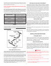
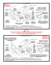
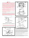
DIRECT VENTING
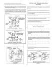
The air intake provided on the unit contains a mesh screen (see Figure 7)
to prevent large particles from entering the unit.
FIGURE 7.
WARNING
WHEN THE UNIT IS TO BE SETUP AS A DIRECT VENT, THE MESH
SCREEN MUST BE REMOVED. THE INLET VENT PIPE MAY THEN BE
GLUED TO THE AIR INTAKE (see Figure 8) PROVIDED ON THE UNIT.
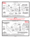
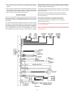
DIRECT VENT TERMINAL INSTALLATION
IMPORTANT
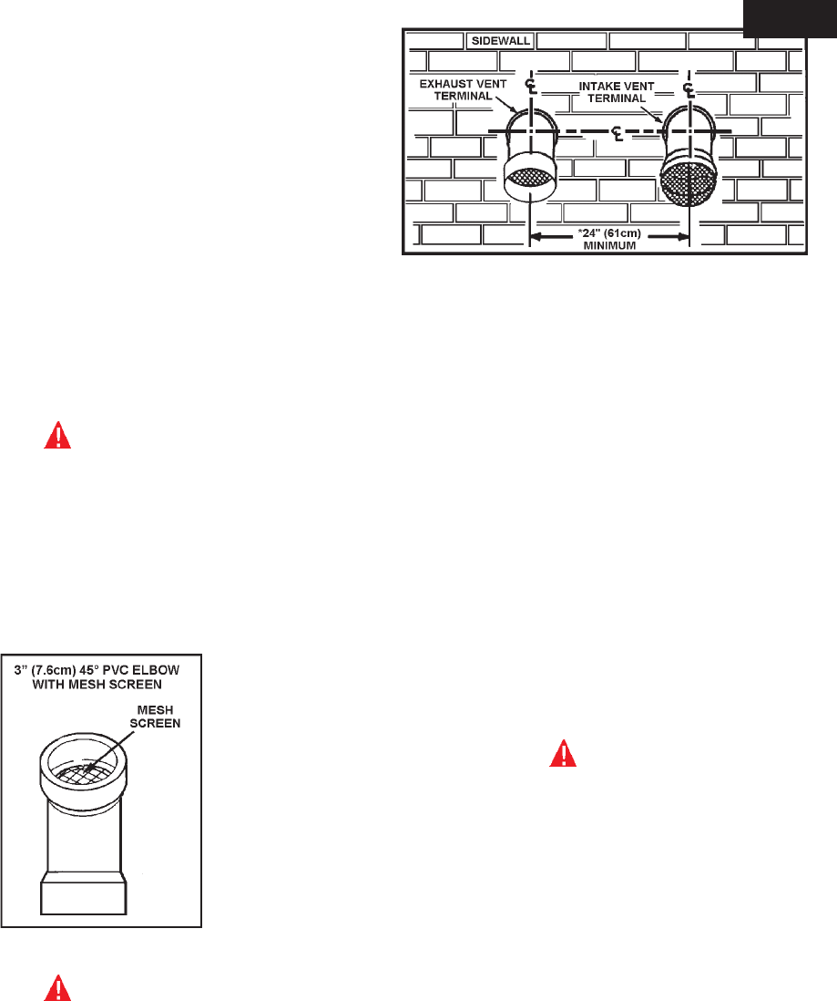
THIS UNIT CONSISTS OF TWO VENT TERMINALS - AN INTAKE VENT
TERMINAL AND AN EXHAUST VENT TERMINAL. THE INTAKE VENT
TERMINAL IS A 3" 45° PVC ELBOW WITH A DOME MESH WIRE SCREEN
AND THE EXHAUST VENT TERMINAL IS A 3" 45°PVC ELBOW WITH A
MESH WIRE SCREEN.
NOTE: TO PREVENT EXHAUSTING PRODUCTS FROM CIRCULATING TO
THE AIR INTAKE IN WINDY/COLD AREAS, THE MAXIMUM PRACTICAL
DISTANCE BETWEEN THESE TWO TERMINALS IS RECOMMENDED
FIGURE 8.
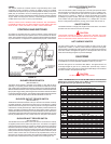
IMPORTANT
WHEN LOCATING THE TERMINALS ON A SIDEWALL, THE FOLLOWING
SPECIFICATIONS PERTAINING TO TERMINAL LOCATION MUST BE
FOLLOWED.
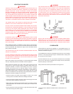
1. The intake vent terminal and the exhaust vent terminal must terminate on
the same exterior wall and must be located at a minimum of 24" (61cm)
from the vertical centerline of the exhaust vent terminal (see Figure 9). In
colder climates increasing the 24" (61cm) minimum will reduce possibility
of frost over from side winds blowing exhaust vapors to the air intake of
the direct vent.
2. The horizontal centerline of the intake vent terminal may not be located
lower than the horizontal centerline of the exhaust vent terminal
(see Figure 9).
INSTALLATION SEQUENCE
For installations in the City of Los Angeles, California Category IV PVC Pipe
such as that manufactured by Brownline Pipe Company, must be used as
vent pipe material
CAUTION
Vent terminals supplied with the heater must be used.
NOTE: BEFORE BEGINNING INSTALLATION OF ANY VENT PIPE READ
THE VENT PIPE MANUFACTURER'S INSTALLATION INSTRUCTIONS.
1. After the points of termination have been determined, use the cover plates
as templates to mark the holes for the vent pipes to be inserted through
the wall. BEWARE OF CONCEALED WIRING AND PIPING INSIDE OF
WALL.
2. If the vent terminals are being installed on the outside of a nished wall, it
may be easier to mark both the inside and outside wall. Align the holes by
drilling a hole through the center of the template from the inside through
to the outside. The template can now be positioned on the outside wall
using the drilled holes as a centering point for the template.
3. A) MASONRY SIDE WALLS
Chisel an opening approximately 1/2" (1.3 cm) larger than the marked
circle.
B) WOODEN SIDE WALLS
Drill a pilot hole approximately one quarter inch outside of the marked
circle. This pilot hole is used as a starting point for a saws-all or sabre saw
blade. Cut around the marked circle staying approximately one quarter
inch outside of the line. (This will allow the vent pipe to easily slide through
the opening. The resulting gap will be covered by the vent terminal cover
plates.) Repeat this step on the inside wall if necessary.
4. Cut a length of 3" PVC pipe about 3.5" (8.9 cm) longer than the wall
thickness at the opening.
FOR ALL
MODELS