


12
Propane Installation Code which requires the vent system components
be certied to ULC S636.
This water heater has been design certied to be vented with PVC pipe
certied and marked as complying with ULC S636. This water heater is
supplied with a 2 inch 22.5 degree termination elbow that is a special tting
that must be used with the appliance. Any outlet piping, ttings and glue used
to vent this appliance that is not supplied by the manufacturer must comply
with the ULC S636 requirements.
PVC Materials should use ASTM D-2564 Grade Cement; CPVC Materials
should use ASTM F-493 Grade Cement and ABS Materials should use ASTM
D-2235 Grade Cement.
If the water heater is being installed as a replacement for an existing power
vented heater in pre-existing venting, a thorough inspection of existing venting
system must be performed prior to any installation work. Verify that correct
material as detailed above has been used, and that the minimum or maximum
vent lengths and terminal location as detailed in this manual have been met.
Carefully inspect the entire venting system for any signs of cracks or fractures,
particularly at joints between elbows and other ttings and straight runs of
vent pipe. Check system for signs of sagging or other stresses in joints as
a result of misalignment of any components in the system. If any of these
conditions are found, they must be corrected in accordance with the venting
instructions in this manual before completing installation and putting the water
heater into service.
NOTE: for Water Heaters in locations with high ambient temperatures (above
100°F or 38°C) and/or insufcient dilution air, it is recommended that CPVC or
ABS pipe and ttings (MUST USE SUPPLIED VENT TERMINAL) be used.
NOTE: Stress levels in the pipe and ttings can be signicantly increased by
improper installation. If rigid pipe clamps are used to hold the pipe in place,
or if the pipe cannot move freely through a wall penetration, the pipe may
be directly stressed, or high thermal stresses may be formed when the pipe
heats up and expands. Install accordingly to minimize such stresses.
VENT PIPE PREPARATION
1. INITIAL PREPARATION
A. Make sure the solvent cement you are planning to use is designed
for the specic application you are attempting.
B. Know the physical and chemical characteristics and limitations of
the PVC, PVC cellular core, ABS or CPVC piping materials that you
are about to use.
C. Know the reputation of your pipe and cement manufacturer and
their products.
D. Know your own qualications or those of your contractor. The solvent
welding technique of joining PVC, PVC cellular core, ABS or CPVC
pipe is a specialized skill just as any other pipe tting technique.
E. Closely supervise the installation and inspect the nished job before
start-up.
F. Contact the manufacturer, supplier, or competent consulting agency
if you have any questions about the application or installation of
PVC, PVC cellular core, ABS or CPVC pipe.
G. Take the time and effort to do a professional job. Shortcuts will only
cause you problems and delays in start-up. The majority of failures
in these systems are the result of shortcuts and/or improper joining
techniques.
2. SELECTION OF MATERIALS
PRIMER
It is recommended that Tetrahydrofuran (THF) be used to prepare the surfaces
of pipe and ttings for solvent welding. Do not use water, rags, gasoline or
any other substitutes for cleaning PVC cellular core, ABS or CPVC surfaces.
A chemical cleaner such as MEK may be used.
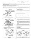
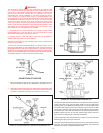
INSTALLATION OF VENT SYSTEM
WARNING
THE OPTIONAL INTAKE VENTING ARRANGEMENT AND THE EXHAUST
VENTING ARRANGEMENT MUST BE INSTALLED TO RUN DIRECTLY TO
THE OUTDOORS AND NOT IN ANY WAY BE CONNECTED TO ANOTHER
VENTING SYSTEM (I.E. FURNACE, DRYERS OR SPACE HEATERS). IT
IS CRUCIAL THAT THE VENTING ARRANGEMENT BE KEPT SEPARATE
FROM OTHER VENTING SYSTEMS. IF THIS WARNING IS IGNORED, AND
THE SYSTEM IS VENTED INCORRECTLY, IT MAY CAUSE IMPROPER
OPERATION, FIRE, EXPLOSION, OR ASPHYXIATION.
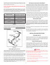
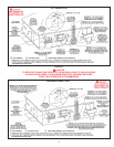
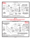
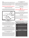
1. Plan the route of the vent system from the vent termination to the planned
location of the appliance. Layout the total vent system to use the minimum
of vent pipe and elbows possible.
2. The installer may add up to a MAXIMUM OF FIFTY (50) EQUIVALENT
FEET (15.2 m) of pipe to the exhaust venting arrangement. This addition
of FIFTY (50) EQUIVALENT FEET (15.2 m) of pipe on both the intake
venting arrangement and exhaust venting arrangement must include any
3" PVC elbows which equals (5) EQUIVALENT FEET (1.5 m) of pipe.
3. It is important that condensate not be allowed to buildup in the exhaust
vent pipe. To prevent this from happening the pipe should be installed with
a slight, 1/8" (3mm) per 5' (152 cm) of pipe maximum downward slope.
4. The vent system should be supported every 5' (152 cm) of vertical run
and every 3' (91cm) of horizontal run of vent pipe length.
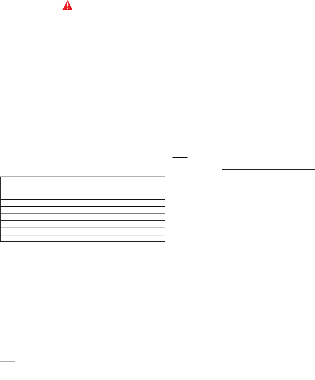
Table 2. VENT LENGTH TABLE
Number 3" 3" 4"
of 90° Minimum Maximum Maximum
Elbows Pipe (Ft./M.) Pipe (Ft./M.) Pipe (Ft./M.)
ONE (1) 7/2 45/13.7 115/35
TWO (2) 7/2 40/12.2 110/33.5
THREE (3) 7/2 35/10.7 105/32
FOUR (4) 7/2 30/9.1 100/30.5
FIVE (5) 7/2 --- 95/29
SIX (6) 7/2 --- 90/27.4
4" PVC may be used for a MAXIMUM intake of ONE HUNDRED TWENTY
(120) EQUIVALENT FEET (36.6m) and a MAXIMUM exhaust of ONE
HUNDRED TWENTY (120) EQUIVALENT FEET (36.6m). The maximum
number of 90° elbows with the 4" venting is six (6) on the intake and six (6)
on the exhaust. A 90° elbow is equal to ve (5) equivalent feet (1.5m) of pipe.
One (1) 90° elbow is equal to two (2) 45° elbows. Any venting conguration
using less than 50 equivalent feet should use 3" venting. See Table 2.
The 3" venting terminals (provided) must be used with the
3" vent pipe. Two, approved 4" vent terminals (not provided) must be used
with 4" vent pipe. See replacement parts list for terminals.
IMPORTANT
When multiple units are direct vented through a wall (3" or 4" venting), all intake
vent terminals should be no lower than the highest exhaust vent terminal.
U.S. INSTALLATIONS
NOTE: This unit can be vented using only PVC (Class 160, ASTM D-2241
Schedule 40, ASTM D-1785 ; or Cellular Core Schedule 40 DWV, ASTM
F-891) , Schedule 40 CPVC (ASTM F-411), or ABS (ASTM D-2661) pipe.
The ttings, other than the TERMINATIONS should be equivalent to PVC-
DWV ttings meeting ASTM D-2665 (Use CPVC ttings, ASTM F-438 for
CPVC pipe and ABS ttings, ASTM D-2661/3311 for ABS pipe. If CPVC or
ABS pipe and ttings are used, then the proper cement must be used for
all joints, including joining the pipe to the Termination (PVC Material). PVC
Materials should use ASTM D-2564 Grade Cement; CPVC Materials should
use ASTM F-493 Grade Cement and ; ABS Materials should use ASTM
D-2235 Grade Cement.
CANADIAN INSTALLATIONS
This water heater must comply with CAN/CSA B149.1 - Natural Gas and