


11
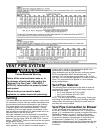
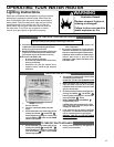
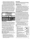
WATER SYSTEM PIPING
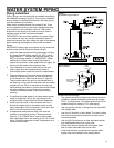
FIGURE 8
Typical Water Piping Installation
FIGURE 9
Typical Tempering
Valve Installation
Tempered Water
to fixtures
Cold
Water
Inlet
Tempering Valve
(set to 120°F
or lower)
Piping Installation
Piping, fittings, and valves should be installed according to
the installation drawing (Figure 8). If the indoor installation
area is subject to freezing temperatures, the water piping
must be protected by insulation.
Water supply pressure should not exceed 80 psi. If this
occurs a pressure limiting valve with a bypass may need
to be installed in the cold water inlet line. This should
be placed on the supply to the entire house in order to
maintain equal hot and cold water pressures.
IMPORTANT: Heat cannot be applied to the water fittings
on the heater as they may contain nonmetallic parts. If
solder connections are used, solder the pipe to the adapter
before attaching the adapter to the hot and cold water
fittings.
IMPORTANT: Always use a good grade of joint compound
and be certain that all fittings are drawn up tight.
1. Install the water piping and fittings as shown in Figure
8. Connect the cold water supply (3/4” NPT) to the
fitting marked “C”. Connect the hot water supply (3/4”
NPT) to the fitting marked “H”. IMPORTANT: Some
models may contain energy saving heat traps to
prevent the circulation of hot water within the pipes. Do
not remove the inserts within the heat traps.
2. The installation of unions in both the hot and cold
water supply lines is recommended for ease of
removing the water heater for service or replacement.
3. The manufacturer of this water heater recommends
installing a tempering valve or an anti-scald device
in the domestic hot water line as shown in Figure 9.
These valves reduce the point of use temperature of
the water by mixing cold and hot water and are readily
available for use. Point of use devices for reducing
scald hazards that attach to faucets and shower heads
are also available from plumbing supply houses.
Contact a licensed plumber or the local plumbing
authority.
4. If installing the water heater in a closed water system,
install an expansion tank in the cold water line as
specified under “Closed System/Thermal Expansion”.
5. Install a shut-off valve in the cold water inlet line. It
should be located close to the water heater and be
easily accessible. Know the location of this valve and
how to shut off the water to the heater.
6. A temperature and pressure relief valve must be
installed in the opening marked “Temperature and
Pressure (T & P) Relief Valve” on the water heater.
Add a discharge line to the opening of the T & P relief
valve. Follow the instructions under Temperature and
Pressure Relief Valve”.
Please note the following:
• The system should be installed only with piping that is
suitable for potable (drinkable) water such as copper,
CPVC, or polybutylene. This water heater must not be
installed using iron piping or PVC water piping.
• Use only pumps, valves, or fittings that are compatible
with potable water.
• Use only full flow ball or gate valves. The use of valves
that may cause excessive restriction to water flow is
not recommended.
• Use only 95/5 tin-antimony or other equivalent solder.
Any lead based solder must not be used.
• Piping that has been treated with chromates, boiler
seal, or other chemicals must not be used.
• Chemicals that may contaminate the potable water
supply must not be added to the piping system.