


20
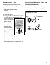
Replacing the Manifold Assembly
1. Check the door gasket for damage or embedded
debris prior to installation.
2. Inspect the viewport for damage and replace as
required.
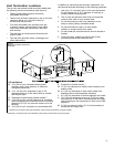
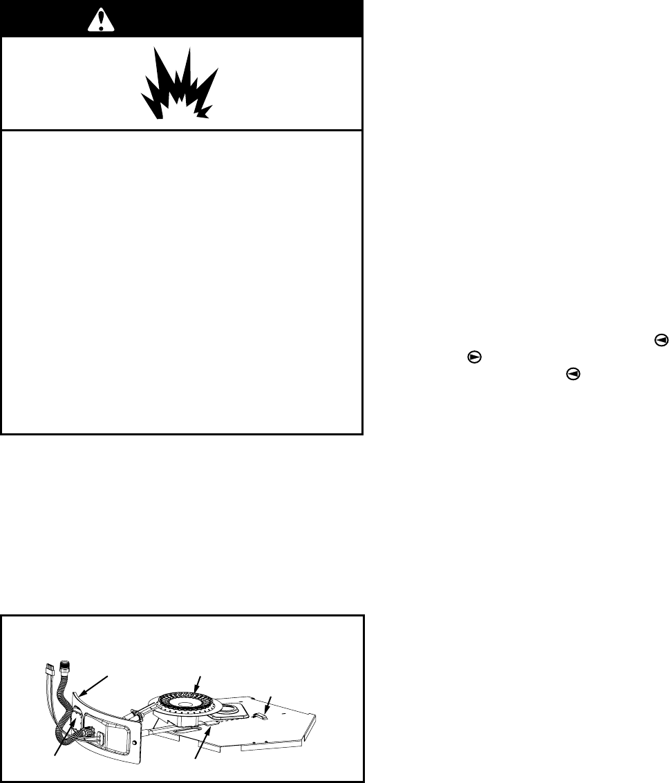
3. Insert the manifold assembly into the burner
compartment making sure that the manifold tab
engages the slot inside the combustion chamber.
See Figure 18.
4. Inspect the door gasket and make sure there is no
fiberglass insulation between the door gasket and the
combustion chamber.
5. Replace the two screws, which secure the manifold
assembly door to the combustion chamber and
tighten securely. Once the manifold assembly door is
tightened, visually inspect the door gasket between
the manifold assembly door and the combustion
chamber for spaces or gaps that would prevent a
seal. IMPORTANT: Do not operate the water heater if
the door gasket does not create a seal between the
manifold door and the combustion chamber.
6. Reconnect the manifold tubing to the thermostat. Do
not cross-thread or apply any thread sealant to the
manifold tubing.
NOTE: L.P. gas systems use reverse (left-hand) threads
on the manifold tube.
7. Reconnect the Flame Sense/Hot Surface Igniter wire
to the thermostat.
8. Turn gas supply on and refer to the Lighting
Instructions.
9. Check for leaks by brushing on an approved
noncorrosive leak detection solution. Bubbles will show
a leak. Correct any leak found.
10. Replace the outer door.
Removing and Replacing the Gas
Control Valve/Thermostat
IMPORTANT: Use only factory authorized replacement parts.
Removing the Gas Control Valve/Thermostat:
1. Set the gas control valve/thermostat to its lowest
setting by first depressing the COOLER
and
HOTTER
buttons together
and hold for 1 second.
Then press the COOLER
button until the WARM
indicator light appears.
(Figure 13).
2. Unplug the water heater from the wall outlet.
3. Turn off the gas at the manual shut-off valve on the
gas supply pipe (Figure 2).
4. Drain the water heater. Refer to the “Draining and
Flushing” section and follow the procedure.
5. Disconnect the flame sense/hot surface igniter wire
from the thermostat. Disconnect the manifold tube at
the thermostat (Figure 16). NOTE: L.P. gas systems
use reverse (left-hand) threads on the manifold tube.
6. Refer to “Gas Piping” (Figure 2) and disconnect the
ground joint union in the gas piping. Disconnect the
remaining pipe from the gas control valve/thermostat.
7. To remove the gas control valve/thermostat, thread a
correctly sized pipe into the inlet and use it to turn the
gas control valve/thermostat (counterclockwise.) Do not
use pipe wrench or equivalent to grip body. Damage
may result, causing leaks. Do not insert any sharp
objects into the inlet or outlet connections. Damage to
the gas control valve/thermostat may result.
Replacing the Gas Control Valve/Thermostat:
To replace the gas control valve/thermostat,
reassemble in reverse order. Use only factory
authorized replacement parts.
• Be sure to use approved Teflon
®
tape or pipe joint
compound on the gas piping connections and fitting
on the back of the gas control valve/thermostat that
screws into tank.
• Turn gas supply on and check for leaks. Use a
chloride-free soap and water solution (bubbles forming
indicate a leak) or other approved method.
• Be sure tank is completely filled with water before
lighting and activating the water heater. Follow the
Lighting Instructions.
• If additional information is required, contact the Service
Department at: 1-800-456-9805.
TEFLON
®
is a registered trademark of E.I. Du Pont De Nemours and Company.
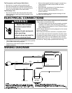
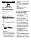
Explosion Hazard
Tighten both manifold door screws
securely.
Remove any fiberglass between gasket
and combustion chamber.
Replace viewport if glass is missing or
damaged.
Replace two piece wire connector if missing
or removed.
Replace door gasket if damaged.
Failure to follow these instructions can
result in death, explosion, or fire.
WARNING
FIGURE 18
Manifold Tab
Burner
Manifold Tab
Slot
Viewport
Door Gasket