


17
Operational Conditions
Condensation
Moisture from the products of combustion condenses on
the tank surface and the outside jacket of the water heater
and forms drops of water which may fall onto the burner or
other hot surfaces. This will produce a “sizzling” or “frying”
noise. This condensation is normal and should not be
confused with a leaking tank. Condensation may increase
or decrease at different times of the year.
High effi cient energy saver water heaters will produce
larger amounts of condensation on initial start-up or
when a large amount of hot water is being used. Do not
confuse this with a “tank leak”. Once the water reaches
a temperature of 120°F (49°C) and the tank warms up
(usually 1-2 hours), the condensation will stop.
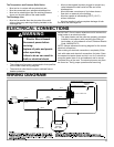
CAUTION - PROPERTY DAMAGE HAZARD
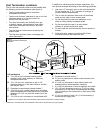
IMPORTANT: It is always recommended that a suitable
metal drain pan be installed under the water heater
to protect the area from water damage resulting from
normal condensation production, a leaking tank or piping
connections. Refer to “Location Requirements” section
Water Heater Sounds
During the normal operation of the water heater, sounds or
noises may be heard. These noises are common and may
result from the following:
1. Normal expansion and contraction of metal parts
during periods of heat-up and cool-down.
2. Condensation causes sizzling and popping within the
burner area and should be considered normal.
3. Sediment buildup in the tank bottom will create
varying amounts of noise and may cause premature
tank failure. Drain and fl ush the tank as directed
under “Draining and Flushing”.
Smoke/Odor
The water heater may give off a small amount of smoke
and odor during the initial start-up of the unit. This is due to
the burning off of oil from metal parts of a new unit and will
disappear after a few minutes of operation.
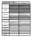
Safety Shut-off
This water heater is designed to automatically shut-off in
the event of the following:
1. The water temperature exceeds 180°F (83°C.)
2. A blockage occurs in the combustion chamber air inlet,
the fl ue gas exhaust outlet, or both the inlet and outlet.
3. The blower fails to operate or operates improperly.
A high temperature limit switch or ECO (Energy Cut Off) in
the tank is used to shut off the unit if the water temperature
exceeds 180°F (83°C.) The ECO is a single use switch and
requires complete replacement of the entire thermostat.
If the ECO should actuate, the water heater cannot be
used until the thermostat is replaced by a qualifi ed person.
Contact your local dealer for service information.
Anode Rod/Water Odor
Each water heater contains at least one anode rod, which
will slowly deplete while protecting the glass-lined tank
from corrosion and prolonging the life of the water heater.
Once the anode is depleted, the tank will start to corrode,
eventually developing a leak. Certain water conditions will
cause a reaction between this rod and the water. The most
common complaint associated with the anode rod is a “rotten
egg smell” produced from the presence of hydrogen sulfide
gas dissolved in the water. IMPORTANT: Do not remove this
rod permanently as it will void any warranties. The parts list
includes a special anode that can be ordered if water odor
or discoloration occurs. NOTE: This rod may reduce but not
eliminate water odor problems. The water supply system
may require special aeration or chlorination equipment from
a water conditioning company to successfully eliminate all
water odor problems.
The use of a water softener may decrease the life of the
water heater tank.
The anode rod should be removed from the water heater
tank every 3 years for inspection. The following are typical
(but not all) signs of a depleted anode rod:
• The majority of the rods diameter is less than 3/8”.
• Signifi cant sections of the support wire (approx. 1/3 or
more of the anode rod’s length) are visible.
If the anode rod show signs of either or both it should be
replaced. NOTE: Whether re-installing or replacing the
anode rod, check for any leaks and immediately correct if
found.
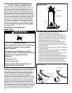
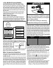
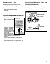
In replacing the anode:
1. Turn off gas supply to the water
heater.
2. Shut off the water supply and
open a nearby hot water faucet to
depressurize the water tank.
3. Drain approximately 5 gallons
of water from tank (Refer to the
“Draining and Flushing” section for
proper procedures). Close drain
valve.
4. Remove old anode rod.
5. Use Tefl on
®
tape or approved pipe
sealant on threads and install new
anode rod.
6. Turn on water supply and open
nearby hot water faucet to purge air
from water system. Check for any
leaks and immediately correct any if found.
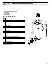
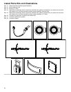
7. Restart the water heater as directed under the
“Operating Your Water Heater” section. See the “Repair
Parts Illustration” section for anode rod location.
TEFLON
®
is a registered trademark of E.I. Du Pont De Nemours and Company.
30 seconds if no further buttons are pressed. After 30
seconds the control will go back to “Sleep” mode.
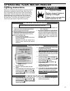
2. Release both of the temperature adjustment buttons.
A. To decrease the temperature press and release the
“COOLER” button until the desired setting is reached.
B. To increase the temperature press and release the
“HOTTER” button until the desired setting is reached.
NOTE: Holding down the button will not continue to lower or
raise the temperature setting. The button must be pressed
and released for each temperature change desired.
Should overheating occur or the gas supply fail to shut off,
turn off the manual gas control valve to the appliance.
NOTE: During low demand periods when hot water is not
being used, a lower thermostat setting will reduce energy
losses and may satisfy your normal hot water needs. If hot
water use is expected to be more than normal, a higher
thermostat setting may be required to meet the increased
demand. When leaving your home for extended periods
(vacations, etc.) turn the temperature dial to its lowest
setting. This will maintain the water at low temperatures
with minimum energy losses and prevent the tank from
freezing during cold weather.
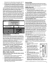
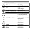
Temperature Setting
Display
A B C
C - Flashing = approx. 160°F
C = approx. 150°F
B = approx. 140°F
A = approx. 130°F
= approx. 120°F
WARM = approx. 80°F
Figure 13
Gas Valve/
Thermostat Settings