


14
INSTALLATION CHECKLIST
Water Heater Location
• Centrally located with the water piping system.
Located as close to the gas piping and vent pipe
system as possible.
• Located indoors and in a vertical position. Protected
from freezing temperatures.
• Proper clearances from combustible surfaces
maintained and not installed directly on a carpeted
fl oor.
• Provisions made to protect the area from water
damage. Drain pan installed and piped to an
adequate drain.
• Installation area free of corrosive elements and
fl ammable materials.
• Suffi cient room to service the water heater.
Gas Supply and Piping
• Gas supply is the same type as listed on the water
heater data plate.
• Gas line equipped with shut-off valve, union, and
drip leg.
• Approved pipe joint compound used.
• Adequate pipe size and of approved material.
• Chloride-free soap and water solution or other
approved means used to check all connections and
fi ttings for possible gas leaks.
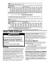
Vent Pipe System
• Vent pipe and fittings of approved material.
• Acceptable size, length, and number of elbows on
air inlet pipe.
• Acceptable size, length, and number of elbows on
exhaust outlet pipe.
• Installed in accordance with prevailing provisions of
local codes, or in the absence of such, National Fuel
Gas Code, NFPA 54, ANSI Z223.1-Current Edition.
• Slope 2” & 3” horizontal piping at a downward pitch
of 1/8” per 5ft. away from the water heater.
• Not obstructed in any way.
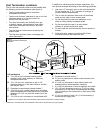
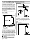
Vent Termination
Concentric
• 12” Min. above grade/snow level.
• Slope exhaust outlet/air inlet piping at a downward
pitch of 1/8” per 5ft. away from the water heater.
Horizontal
• Correct relationship - outlet to inlet.
• 12” Min. above grade/snow level.
• Slope 2” & 3” horizontal piping at a downward pitch
of 1/8” per 5ft. away from the water heater.
• Away from corners, other vents, windows, etc.
Vertical
• Inlet - 12” Min. above roof/snow level.
• Correct relationship - outlet to inlet.
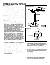
Water System Piping
• Temperature and pressure relief valve properly
installed with a discharge line run to an open drain and
protected from freezing.
• All piping properly installed and free of leaks.
• Heater completely fi lled with water.
• Closed system pressure build-up precautions
installed.
• Tempering valve installed per manufacturer’s
instructions, when applicable. (See page 16.)
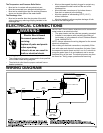
Electrical Connections
• Unit connected to a dedicated power supply.
• Unit connected to a 120V electrical supply.
• Proper polarity.
• Water heater properly grounded.
• Installed in accordance with prevailing provisions of
local codes, or in the absence of such, the current
edition of the National Electric Code, ANSI/NFPA 70.