


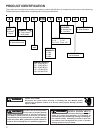
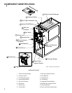
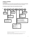
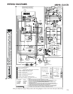
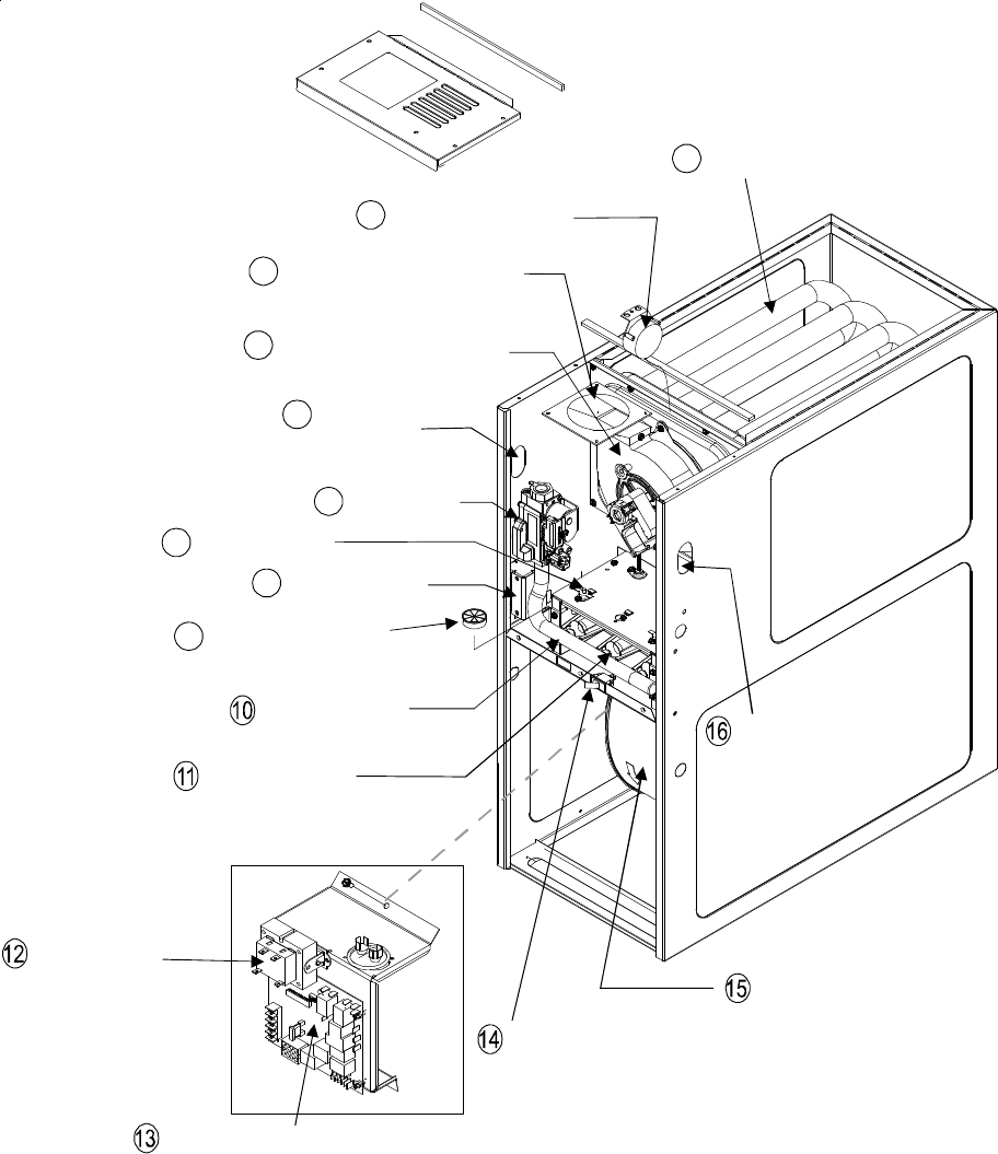
COMPONENT IDENTIFICATION
6
躀
Pressure Switch
Tubular Heat Exchanger
Flue Pipe Connection
Gas Line Entrance
(Alternate)
Induced Draft Blower
Gas Line
Entrance
Gas Valve
Rollout Limit
Junction Box
Wiring Harness
Grommet
Gas Manifold
Inshot Burner
Blower Door
Interlock Switch
Integrated Control Module
Transformer
Circulator Blower
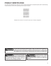
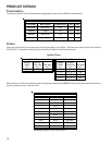
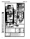
1
2
3
4
5
6
7
8
9
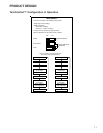
Upflow/Horizontal
1 Tubular Heat Exchanger
2 Pressure Switch
3 Flue Pipe Connection
4 Induced Draft Blower
5 Gas Line Entrance
6 Gas Valve
7 Rollout Limit
8 Junction Box
9 Wiring Harness Grommet
10 Gas Manifold
11 Inshot Burner
12 Transformer
13 Integrated Control Module
14 Blower Door Interlock Swtich
15 Circulator Blower
16 Gas Line Entrance (Alternate)
Note: Primary Limit Not Shown