


4
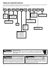
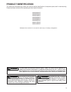
PRODUCT DESIGN
WARNI NG
T
O PREVENT POSSIBLE PERSONAL INJURY OR DEATH DUE TO ASPHYXIATION,
THIS FURNACE MUST BE
C
ATEGORY
I
VENTED.
D
O NOT VENT USING
CATEGORY III VENTING.
1. Category I Venting is venting at a non-positive pressure.
A furnace vented as Category I is considered a fan-as-
sisted appliance and the vent system does not have to
be “gas tight.” NOTE: Single stage gas furnaces with
induced draft blowers draw products of combustion
through a heat exchanger allowing, in some instances,
common venting with natural draft appliances (i.e. water
heaters). All installations must be vented in accordance
with National Fuel Gas Code NFPA 54/ANSI Z223.1 -
latest edition. In Canada, the furnaces must be vented in
accordance with the National Standard of Canada, CAN/
CSA B149.1 and CAN/CSA B149.2 - latest editions and
amendments.
NOTE: The vertical height of the Category I venting system
must be at least as great as the horizontal length of the
venting system.
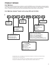
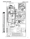
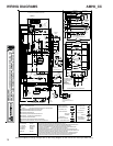
2. Line voltage wiring can enter through the right or left side
of the furnace. Low voltage wiring can enter through the
right or left side of furnace.
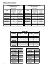
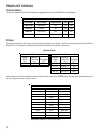
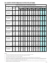
3. Conversion kits for propane gas and high altitude natural
and propane gas operation are available. See High Alti-
tude Derate chart for details.
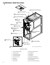
General Operation
The AMH8 furnaces are equipped with an electronic ignition
device used to light the burners and an induced draft blower
to exhaust combustion products.
An interlock switch prevents furnace operation if the blower
door is not in place. Keep the blower access door in place
except for inspection and maintenance.
This furnace is also equipped with a self-diagnosing elec-
tronic control module. In the event a furnace component is
not operating properly, the control module LED will flash on
and off in a factory-programmed sequence, depending on
the problem encountered. This light can be viewed through
the observation window in the blower access door. Refer to
the Troubleshooting Chart for further explanation of the LED
codes and Abnormal Operation - Integrated Ignition Control
section in the Service Instructions for an explanation of the
possible problem.
The rated heating capacity of the furnace should be greater
than or equal to the total heat loss of the area to be heated.
The total heat loss should be calculated by an approved
method or in accordance with “ASHRAE Guide” or “Manual
J-Load Calculations” published by the Air Conditioning Con-
tractors of America.
*Obtain from: American National Standards Institute 1430
Broadway New York, NY 10018
Location Considerations
• The furnace should be as centralized as is practical
with respect to the air distribution system.
• Do not install the furnace directly on carpeting, tile, or
combustible material other than wood flooring.
• When suspending the furnace from rafters or joists,
use 3/8" threaded rod and 2” x 2” x 3/8” angle as
shown in the Installation and Service Instructions. The
length of the rod will depend on the application and
clearance necessary.
• When installed in a residential garage, the furnace
must be positioned so the burners and ignition source
are located not less than 18 inches (457 mm) above
the floor and protected from physical damage by ve-
hicles.