


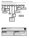
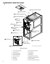
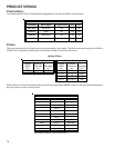
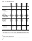
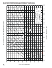
FURNACE SPECIFICATIONS
12
NOTES:
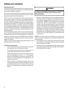
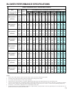
1. For elevations above 2000 feet the rating should be reduced by 4% for each 1000 feet above sea level. The furnace must not be derated,
orifice changes should only be made if necessary for altitude.
2. The total heat loss from the structure as expressed in TOTAL BTU/HR must be calculated by the manufacturers method or in accordance with
the "A.S.H.R.A.E. GUIDE" or "MANUAL J-LOAD CALCULATIONS" published by the AIR CONDITIONING CONTRACTORS OF AMERICA. The total
heat loss calculated should be equal to or less than the heating capacity. Output based on D.O.E. test procedures, steady state efficiency times
output.
1. These furnaces are manufactured for natural gas operation. Optional kits are available for conversion to propane operation.
2. Minimum Circuit Ampacity calculated as: (1.25 x Circulator Blower Amps) + I.D. Blower Amps. Wire sizes should be determined in accordance
with National Electrical Codes.Extensive wire runs will require larger wire sizes.
3 Maximum Overcurrent protections Device refers to maximum recommended fuse or circult breaker size. May use time delay fuses or HACR-
type circuit breakers of the same sizes as noted.
*Off Heating - This fan delay timing is adjustable (90, 120, 150 or 180 seconds). 150 seconds as shipped.
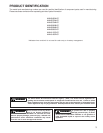
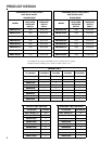
MODEL
AMH80453AX**
AMH80703AX**
AMH80704BX**
AMH80903BX**
AMH80904BX**
AMH80905CX**
AMH81155CX**
AMH81405DX**
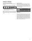
Input, Natural Gas (BTUH) 45,000 70,000 70,000 90,000 90,000 90,000 115,000 140,000
Output, Natural Gas (BTUH)
1
36,000 56,000 56,000 72,000 72,000 72,000 92,000 112,000
Output, LP (BTUH) 32,000 48,000 48,000 64,000 64,000 64,000 80,000 96,000
A.F.U.E. 80.0% 80.0% 80.0% 80.0% 80.0% 80.0% 80.0% 80.0%
Rated External Static (" w.c.) 0.20 - 0.50 0.20 - 0.50 0.20 - 0.50 0.20 - 0.50 0.20 - 0.50 0.20 - 0.50 0.20 - 0.50 0.20 - 0.50
Temperature Rise (°F) 25 - 55 25 -55 20 - 50 35 - 65 35 - 65 35 - 65 35 - 65 40 - 70
Pressure Switch Trip Point (" w.c.) -0.70 -0.70 -0.75 -0.75 -0.75 -0.75 -0.90 -0.80
Blower Wheel (D" x W") 10x6 10x6 10x8 10x8 10x8 10x10 10x10 11x10
Blower Horsepower 1/3 1/3 1/2 1/3 1/2 1/2 1/2 3/4
Blower Speeds 4 4 4 4 4 4 4 4
Max CFM @ 0.5 E.S.P. 1280 1100 1610 1439 1738 1854 1902 2084
Power Supply (Volts/Hz/Ph) 115/60/1 115/60/1 115/60/1 115/60/1 115/60/1 115/60/1 115/60/1 115/60/1
Minimum Circuit Ampacity (MCA)
2
8.1 8.1 12.5 8.1 12.5 12.5 12.5 14.7
Maximum Overcurrent Device
3
15 15 15 15 15 15 15 15
Transformer (VA) 40 40 40 40 40 40 40 40
Primary Limit Setting (°F) 220 170 170 170 160 180 180 160
Auxiliary Limit Setting (°F) 120 120 120 120 120 120 120 120
Rollout Limit Setting (°F) 300 300 300 300 300 300 300 300
Fan Delay On Heating 30 30 30 30 30 30 30 30
Off Heating * 150 150 150 150 150 150 150 150
Fan Delay On Cooling 5 5 5 5 5 5 5 5
Off Cooling 45 45 45 45 45 45 45 45
Fan Delay On - Fan Only 0 0 0 0 0 0 0 0
Gas Supply Pressure
(
Natural/Pro
p
ane
)
(
" w.c.
)
7 / 11 7 / 11 7 / 11 7 / 11 7 / 11 7 / 11 7 / 11 7 / 11
Manifold Pressure
(
Natural/Pro
p
ane
)
(
" w.c.
)
3.5 / 10 3.5 / 10 3.5 / 10 3.5 / 10 3.5 / 10 3.5 / 10 3.5 / 10 3.5 / 10
Orifice Size (Natural/Propane) 43 / 55 43 / 55 43 / 55 43 / 55 43 / 55 43 / 55 43 / 55 43 / 55
Number of Burners
23344456
Vent Connector Diameter (inches) 4 4 4 4 4 4 4 4
Shipping Weight (lbs.) 115 125 136 146 146 154 154 153