


7
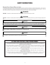
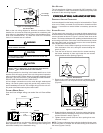
Figure 12 - Horizontal Duct Cover Installation
DUCTWORK
Duct systems and register sizes must be properly designed for the
C.F.M. and external static pressure rating of the unit. Ductwork should
be designed in accordance with the recommended methods of Air
Conditioning Contractors of America Manual D (Residential) or
Manual Q (Commercial). All ductwork exposed to the outdoors must
include a weatherproof barrier and adequate insulation.
A duct system should be installed in accordance with Standards of
the National Board of Fire Underwriters for the Installation of Air Con-
ditioning, Warm Air Heating and Ventilating Systems. Pamphlets No.
90A and 90B.
The warm air supply duct from the unit through a wall fabricated of
combustible material may be installed without clearance. However,
minimum clearances for the unit must be observed as shown in Prod-
uct Data Book applicable to your model*.
The outlet duct should be provided with an access panel.
For vertical airflow, the ductwork should be attached to the roof curb
prior to installing the unit. Ductwork dimensions are shown in the
PRC roof curb installation manual.
If desired, supply and return duct connections to the unit may be
made with flexible connections to reduce possible unit operating
sound transmission.
FILTERS
CAUTION
T
O AVOID PROPERTY DAMAGE DUE TO FIRE AND LOSS OF EQUIPMENT
EFFICIENCY OR EQUIPMENT DAMAGE DUE TO DUST AND LINT BUILD UP ON
INTERNAL PARTS, NEVER OPERATE UNIT WITHOUT A FILTER INSTALLED.
Even though a return air filter is not supplied with this unit, there
must be a means of filtering all return air.
Refer to Product Data Book applicable to your model* for filter size
information.
If using the Over/Under Transition Kit, the filter(s) may be located in
the return air duct(s) or return air filter grille(s). Filters installed exter-
nal to the unit should be sized in accordance with their manufacturer
recommendations. A throwaway filter must be sized for a maximum
face velocity of 300 feet per minute.
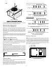
FILTER INSTALLATION
Important: When installing a filter, the air flow arrows on the filter
must point toward the circulating air blower.
COCO
COCO
CO
NDND
NDND
ND
ENSAENSA
ENSAENSA
ENSA
TE DTE D
TE DTE D
TE D
RAINRAIN
RAINRAIN
RAIN
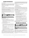
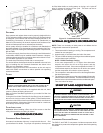
CONDENSATE DRAIN CONNECTION
An external condensate drain trap is required with this unit. See
your distributor for details. For proper unit operation, the trap must
be filled either before a cooling startup or during a unit “cycle-off”
after 20 minutes of running on first cycle. This drain can be ex-
tended using 3/4” PVC piping.
2-1/2" of
3/4" PVC
Condensate
Drain Trap
90° ELL
1-1/2" Minimum
drop at outlet
Figure 13 - Condensate Drain Connection
NONO
NONO
NO
RMRM
RMRM
RM
AL SEQUENAL SEQUEN
AL SEQUENAL SEQUEN
AL SEQUEN
CE OCE O
CE OCE O
CE O
F OPERAF OPERA
F OPERAF OPERA
F OPERA
TITI
TITI
TI
OO
OO
O
NN
NN
N
NOTE: There is a fan delay on initial power to unit before the low
voltage board resets and is operational.
1. Thermostat calls for heating or cooling. The compressor and
outdoor fan are energized.
2. Approximately 10 seconds later, the indoor fan starts.
3. The unit will deliver heating or cooling to the conditioned space
until the thermostat is satisfied.
NOTE: PHD60 Two-Stage Cooling
If the room temperatures is 4°F higher than thermostat
setpoint, the indoor fan will run at high speed, and the
compressor at full load. If the room temperature is within 2°F
of thermostat setpoint; the indoor fan will shift to low speed
and the compressor will unload to a lower capacity.
4. The compressor and outdoor fan will be de-energized when
the thermostat opens.
5. The indoor fan continues to run for approximately 30 seconds
after the thermostat is satisfied. This allows additional cooling
from the indoor coil to be transferred to the conditioned space.
Then, the indoor fan stops.
STST
STST
ST
ARAR
ARAR
AR
TUP AND ADTUP AND AD
TUP AND ADTUP AND AD
TUP AND AD
JUSTJUST
JUSTJUST
JUST
MENTMENT
MENTMENT
MENT
WARNING
T
O PREVENT PERSONAL INJURY OR DEATH, ALWAYS DISCONNECT THE
ELECTRICAL POWER BEFORE INSPECTING OR SERVICING THE UNIT.
S
INCE
ALL OF THE COMPRESSOR PROTECTION DEVICES RESET AUTOMATICALLY,
THE CONTACTOR AND OUTDOOR FAN MAY BE ENERGIZED WHEN RESET.
CAUTION
T
HIS UNIT MUST NOT BE USED AS A "CONSTRUCTION HEATER" DURING
THE FINISHING PHASES OF CONSTRUCTION ON A NEW STRUCTURE.
T
HIS
TYPE OF USE MAY RESULT IN PREMATURE FAILURE OF THE UNIT DUE TO
EXTREMELY LOW RETURN AIR TEMPERATURES AND EXPOSURE TO VERY
DIRTY ATMOSPHERES.
COMPRESSOR PROTECTION DEVICES
The PHB**C and PHD**C compressor includes components which
are designed to protect the compressor against abnormal operating
conditions.