6
A
i
r
f
l
o
w
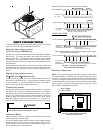
Install Screws
Removed From
Back Panel
Motor Leads MUST
exit at bottom
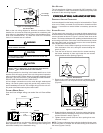
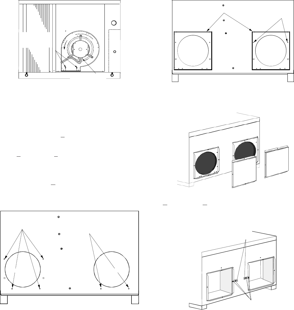
Figure 7 - Vertical Blower Assembly
HORIZONTAL DUCT COVER INSTALLATION
The second step in the downshot airflow conversion is to install Hori-
zontal Duct Covers. Horizontal Duct Covers are an accessory, and
can be purchased from your authorized dealer. The kit number is
CHK001A.
Models 24, 30, 36, 42, and PH
B48 require that the supply and return
air openings be converted to square. Flanges are shipped with these
units to complete this conversion.
Models PH
D48/60 and PHB60 supply and return air openings are
square and do not require a flange conversion. They do, however,
require that cover clips (included with the unit) be installed to ensure
a secure fit of the Horizontal Duct Covers.
24, 30, 36, 42 AND PHB48 MODELS:
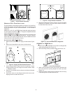
1. Remove and set aside the four supply air side screws (Figure
8).
2. Remove and set aside the two return air side screws.
RETURN AIRSUPPLY AIR
REMOVE
SCREWS
REMOVE
SCREWS
Figure 8 -Supply Air Side Screws Removal
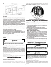
3. Center flange bracket (Figure 9) and unit openings. Attach
flange brackets to the unit using the removed screws in Step
1. Retighten screws.
4. Drill two 1/8” diameter holes on the return air side as indicated
in Figure 9.
5. Secure the return air side flange bracket with the two self-
tapping screws included with the unit.
Drill 2-1/8"
Dia.
holes
FLANGE BRACKETS
SUPPLY AIR RETURN AIR
Figure 9 - Flange Bracket Installation
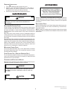
6. Align the horizontal duct covers (Figure 10) over the flange
brackets just installed and secure with screws included in
the Horizontal Duct Cover kit.
Figure 10 - Horizontal Duct Cover Alignment
PHD48/60 AND PHB60 MODELS:
1. Install cover clips (included with unit) on the inner flange sides
using existing flange hole (Figure 11).
2. With self-drilling screws provided, attach clips to the unit.
CLIPS
SELF-DRILLING
SCREWS
Figure 11 - Cover Clip Installation
3. Attach 16x16 horizontal covers using screws provided with
kit to the outer duct opening flange and cover clip holes
(Figure 12).
4. Secure the center of the top flat cover flange to the unit using
a self-drilling screw included with the unit.


