


ENGLISH USER MANUAL
30 FLOORTEC R 680 P 1463514000(1)2008-05 A
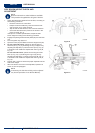
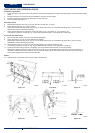
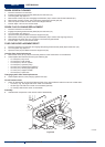
SPARK SCREEN CLEANING
Drive the machine on a level fl oor.1.
Engage the parking brake with the pedal (82) and the lever (75).2.
Turn the ignition key (69) to “0”.3.
Remove the screws (48), then disengage the fasteners (49) to remove the left side bulkhead (47).4.
Remove the mounting screws, then remove the engine exhaust end pipe (53).5.
Clean the spark screen as shown in the Petrol Engine Manual.6.
Perform steps 4 and 5 in the reverse order.7.
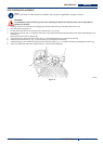
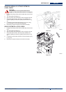
SPARK PLUG CLEANING/REPLACEMENT
Drive the machine on a level fl oor.1.
Engage the parking brake with the pedal (82) and the lever (75).2.
Turn the ignition key (69) to “0”.3.
Open the hood (23) and fasten it with the support rod (55).4.
Remove the screws (45), then disengage the fasteners (46) to remove the engine guard (44).5.
Clean/replace the spark plug (51), as shown in the Petrol Engine Manual.6.
Perform steps 4 and 5 in the reverse order.7.
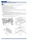
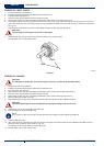
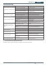
FUSE CHECK/REPLACEMENT/RESET
Drive the machine on a level fl oor and engage the parking brake with the pedal (82) and the lever (75).1.
Turn the ignition key (69) to “0”.2.
Open the hood (23) and fasten it with the support rod (55).3.
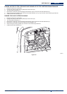
Lamellar fuse check/replacement
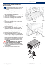
Remove the cover (A, Fig. 29) and mark the positions of the fuses shown on the adhesive.4.
Check/replace the relevant fuse among the following (B):5.
F1 fuse (30 A): Key circuit•
F2 fuse (30 A): Filter shaker•
F3 fuse (30 A): Vacuum system•
F4 fuse (30 A): Hydraulic pump•
F5 fuse (10 A): Flashing light (optional)•
F6 fuse (10 A): Working light (optional)•
F7 fuse (10 A): Hopper actuator•
F8 fuse (30 A): Spare fuse•
Charging system fuse check/replacement
Check/replace the FD (70 A) charging system fuse (50).6.
Circuit breaker check
Check for deactivation of one of the following fuses, then reset it after the relevant motor has cooled down:7.
FA fuse (C, Fig. 29): Right side broom motor circuit breaker•
FB fuse (D): Left side broom motor circuit breaker (optional)•
FC fuse (E): Main broom motor circuit breaker•
Assembly
Assemble the components in the reverse order of disassembly.8.
A
E
C
D
B
P100249
Figure 29