


Page 6 506488-01Issue 1008
Condensate Drain
The PGE/SG package unit is equipped with a 3/4" FPT
coupling for condensate line connection. Plumbing must
conform to local codes. Use a sealing compound on male
pipe threads.
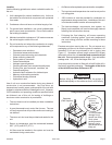
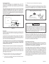
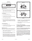
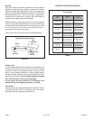
The condensate drain line must be properly trapped and
routed to a suitable drain. See Figure 5 for proper drain
arrangement. The drain line must pitch to an open drain or
pump to prevent clogging of the line. Seal around the drain
connection with suitable material to prevent air leakage into
the return air system.
Ductwork
Ductwork should be designed and sized according to the
methods in Manual Q of the Air Conditioning Contractors of
America (ACCA).
A closed return duct system shall be used. This shall not
preclude use of economizers or outdoor fresh air intake. It
is recommended that supply and return duct connections at
the unit be made with flexible joints.
The supply and return air duct systems should be designed
for the CFM and static requirements of the job. They should
not be sized by matching the dimensions of the duct
connections on the unit.
Outdoor ductwork must be insulated and waterproofed.
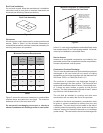
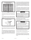
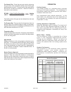
Equipment is shipped for side ductwork connection. The unit
can be converted to bottom ductwork connection by
removing the duct covers located over the bottom duct
openings and placing these covers over the side duct
openings (see Figure 6).
To remove the bottom duct cover over supply opening:
1. Remove screw on cover nearest side opening.
2. Lift end of cover slightly and push to slide back screw/
pin free from duct flange.
3. Slide duct cover out the side duct opening.
Filters
Air filters are to be used with this heating/cooling unit. Filters
are not factory supplied in the unit. However, a filter frame
accessory is available from the manufacturer that allows
filters to be installed within the unit. If the filter frame
accessory is not used, a filter must be installed in the duct
work by the installer. Filters must always be installed ahead
of the evaporator coil and must be kept clean or replaced.
Dirty filters will reduce the airflow of the unit. Filters should
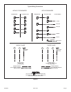
be sized in accordance with Table 2.
Gas Supply and Piping
Refer to the furnace rating plate to make sure the furnace is
equipped to burn the gas supplied (natural or propane). See
LPG/Propane Units, Tanks, and Piping on page 7 for more
information on converting to propane gas.
Gas supply piping should be installed in accordance with
local codes and the regulations of the utility. In the absence
of local codes, the latest edition of the National Fuel Gas
Code ANSI Z223.1 (in the U.S.), or the Natural Gas and
Propane Installation Codes CAN/CGA B149.1 & B149.2 (in
Canada), should be followed. Piping must be of adequate
size to prevent undue pressure drop. Consult the local utility
or gas supplier for complete details on special requirements
for sizing gas piping.
Unit
Drain Connection
Positive Liquid Seal Required
3.00" Min.
1.00" Min.
12.00"
Max.
Typical Condensate Drain Connection
Figure 5
Figure 6
Removing Bottom Duct Covers
Base
1. Remove screw and lift.
2. Slide cover to free back pin.
1
2
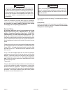
When fastening ductwork to side duct flanges on unit,
insert screws through duct flanges only; do not insert
screws through casing. If using bottom duct work, do
not use screws to secure ductwork to bottom duct
opening under drain pan side. Using screws to secure
bottom duct may damage drain pan.
CAUTION