


Page 10 506488-01Issue 1008
START-UP
Pre-Start Check List
Complete the following checks before starting the unit:
1. Check the type of gas being supplied. Be sure it is the
same as listed on the unit nameplate.
2. Make sure that the vent hood has been properly installed.
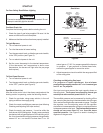
To Light Burners:
1. Turn off electrical power to unit.
2. Turn the thermostat to lowest setting.
3. Turn the gas control knob, or slide the gas control switch,
to the “ON” position (see Figure 9).
4. Turn on electrical power to the unit.
5. Set the room thermostat to the desired temperature.
(If the thermostat “set” temperature is above room
temperature, the burners will light after the pre-purge
time expires.)
To Shut Down Burners:
1. Turn off electrical power to unit.
2. Turn the gas control knob, or slide the gas control switch,
to the “OFF” position (see Figure 9).
Post-Start Check List
After the entire control circuit has been energized and the
heating section is operating, make the following checks:
1. Check for gas leaks, using soapy solution, in the unit
piping as well as the supply piping.
2. Check for correct manifold gas pressures (see following
Checking and Adjusting Gas Input section).
3. Check the supply gas pressure. It must be within the
limits shown on the rating plate. Supply pressure should
be checked with all gas appliances in the building at full
fire. At no time should the supply pressure during standby
exceed 13" w.c., nor should it be less than 5" w.c. for
For Your Safety Read Before Lighting
natural gas or 11" W.C. for propane gas with the burners
in operation. If gas pressure is outside these limits,
contact the gas supplier for corrective action.
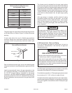
4. Adjust temperature rise to be within the range specified
on the rating plate.
Checking and Adjusting Gas Input
For purpose of input adjustment, the minimum
permissible gas supply pressure is 5" w.c. for natural gas
and 11" w.c. for propane.
Gas input must never exceed the input capacity shown on
the rating plate. The furnace is equipped for natural gas
rated inputs with manifold pressure of 3.5" w.c.
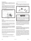
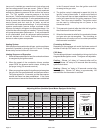
The manifold pressure can be measured by shutting off the
gas, removing the pipe plug in the downstream side of the gas
valve, and connecting a water manometer or gauge. To adjust
the regulator, turn the adjusting screw on the regulator
clockwise to increase pressure and input or counterclockwise
to decrease pressure and input. The final manifold pressure
should not vary more than 0.3" w.c. from the above
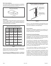
specified pressure. See Figure 9 to assist in locating the
regulator on the gas valve.
Furnace is equipped with a direct ignition control. Do not
attempt to manually light the burners.
CAUTION
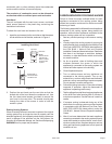
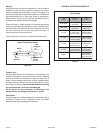
Figure 9
Gas Valves
Regulator
Adjustment
Cap
Gas
Control
Knob
Inlet Pressure Tap
1/8" NPT
Outlet Pressure Tap
(Manifold Pressure)
1/8" NPT
Gas Control Switch
Inlet Pressure Tap
1/8" NPT
Outlet Pressure Tap
(Manifold Pressure)
1/8" NPT
Regulator
Adjustment
Cap