


Page 12 506488-01Issue 1008
in the 10-second interval, then the ignition control will
de-energize the gas valve.
4. The ignition control is designed to repeat this “trial for
ignition” a total of three times. If, at the end of the third
trial, a flame still has not been established, the ignition
control will repeat the trial for ignition sequence 1 hour
later. The 1-hour retry is indefinite. The ignition control
can be reset by interrupting the unit power or the
thermostat circuit.
5. Thirty seconds (nominal) after the initial trial for ignition,
the circulation air blower will start.
6. When the thermostat is satisfied, the combustion blower
and gas valve are de-energized. The circulating air
blower motor will continue to run for a short period after
the thermostat is satisfied.
Circulating Air Blower
Depending on the package unit model, the blower motor will
be either a multi-tap PSC motor or a variable speed motor.
PSC Motor
The circulating air blower is controlled by a timing circuit in the
integrated blower/ignition control. Timings are not adjustable.
Cooling – Blower “on” delay is 5 seconds after call for
cooling. Blower “off” delay is 90 seconds after the cooling
system shuts down.
Heating – Blower “on” delay is 30 seconds nominal after
burner ignition. Blower "off" delay is approximately 120
seconds after the thermostat is satisfied.
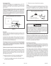
Insure unit is installed per manufacturer’s instructions and
that line voltage and air flows are correct. Refer to Table 3
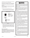
for proper superheat or subcooling values. Check superheat
settings by measuring pressure at the suction line service
port. For TXV systems, measure pressure at the liquid
service port. Take line temperature within 2 inches of service
port connection to its main tube. If unit superheat/subcooling
varies by more than table allowance, check internal seals,
service panels and duct work for air leaks, as well as
restrictions and blower speed settings. If unit performance
remains questionable, remove charge, evacuate to 500
Microns, and weigh in refrigerant to name plate charge. It is
critical that the exact charge is re-installed. Failure to comply
will compromise system performance. If unit performance
is still questionable, check for refrigerant related problems
such as, blocked coil or circuits, malfunctioning metering
devices or other system components.
Heating System
With the proper thermostat and sub-base, continuous blower
operation is possible by closing the R to G circuit. Cooling
blower delay is also functional in this mode.
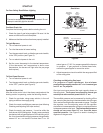
Heating Sequence of Operation
1. When the thermostat calls for heat, the combustion blower
is energized by the ignition control.
2. When the speed of the combustion blower reaches
proper RPM, the pressure switch closes, initiating the
pre-purge timing (30 seconds nominal).
3. When pre-purge has expired, the ignition control energizes
the gas valve, the spark electrode, and the flame sensor.
The igniter sparks for 10 seconds, and the flame sensor
senses that flame has been established. If the flame
sensor does not sense that flame has been established
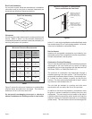
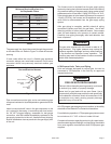
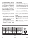
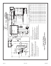
ledoM
rotoM
PH
TSUJDA
gnitteS
TAEH
gnitteS
citatS05.@MFCgnilooC
lanimoN
gnilooC
UTBk
gnitaeH
tupnI
UTBk
LOOC
gnitteS
A
LOOC
gnitteS
B
LOOC
gnitteS
C
LOOC
gnitteS
D
03,42863/1MRONA0001008006009
63 86 2/1 MRON B 0021 0001 008 0011
63092/1MRONA002100010080011
06,84,24 38 4/3 MRON C 0081 0061 0041 0021
06,84,240114/3MRONC0081006100410021
06,84,24 831 4/3 MRON A 0081 0061 0041 0021
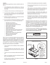
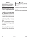
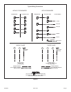
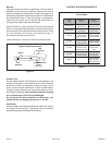
Adjusting Airflow (Variable Speed Motor Equipped Units Only)
Table 4
DEHUMIDIFY
CUT TO ENABLE
COOLHEATADJUST
NORM A
B
C
D
A
B
C
D
(+)
(–)
TEST
D1
ADJUST, HEAT,
and COOL Taps
and Dehumidify
Resistor
on Interface
Board