


506488-01 Page 13Issue 1008
Variable Speed Motor
Units equipped with a variable speed circulation air blower
motor will deliver a constant airflow within a wide range of
external static pressures. Other features of this variable
speed motor include:
Soft Start/Stop – The variable speed motor will slowly ramp
up to normal operating speed. This minimizes noise and
increases comfort by eliminating the initial blasts of air
encountered with standard motors. At the end of a cooling
or heating cycle, the motor will slowly ramp down.
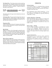
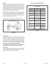
Circulation Airflow Adjustments – The controls include a
variable speed motor interface board. The ADJUST tap can
be used to raise (+) or lower (–) the airflow by 15%.
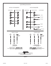
Heating and Cooling Airflows – The units are factory set
for the correct heating and cooling airflows. However, airflow
changes can be made by moving the position of the HEAT
and COOL taps (see Table 4).
Continuous Blower – The comfort level of the living space
can be enhanced when using this feature by allowing
continuous circulation of air between calls for cooling or
heating. The continuous circulation of air occurs at half the
full cooling airflow rate. To use this feature, place the
thermostat fan switch into the ON position.
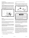
Cooling Airflow Ramp Up – At the beginning of a call for
cooling, the blower will run at 80% of full airflow for 7.5
minutes. This improves the system’s moisture removal and
saves blower power during cooling start.
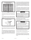
Reduced Airflow Operation (Dehumidification) – For
situations where humidity control is an issue, the variable
speed motor can be connected to operate at a 25% reduction
in the normal airflow rate. The variable speed motor interface
board provides for connection of a humidistat on the HUM
terminal. When a humidistat is connected, the dehumidifier
resistor on the interface must be cut. The humidistat should
be wired to open during high humidity, which will reduce
blower airflow.
Safety Controls
The control circuit includes the following safety controls:
Limit Control
This control is located inside the heating compartment and is
designed to open at abnormally high air temperatures. It resets
automatically. The limit control operates when a high temperature
condition, caused by inadequate airflow, occurs. This causes
the ignition control to close the gas valve. The circulation air
blower continues to operate in this situation.
Pressure Switch
The pressure switch prevents the gas valve and igniter from
being energized if there is insufficient combustion air due to
a failed combustion blower or a blocked vent.
Flame Sensor
If the ignition control does not receive a signal from the flame
sensor indicating that the burners have established flame, the
gas valve closes after the 10-second trial for ignition period.
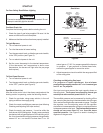
Rollout Switch
The switch is located above the main burners. In the event
of a sustained flame rollout, the rollout switch causes the
ignition control to close the gas valve. To reset, push the
button on top of the switch.
Auxiliary Limit (42, 48, and 60 units only)
This control is located in the side of the circulation air blower
housing. The switch causes the ignition control to close the
gas valve should the circulation blower fail to operate. This
control resets automatically.
It is recommended that this furnace be inspected by a
qualified service technician at the beginning of each heating
season.
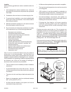
Filters
Filters should be checked at least every 6 weeks. Disposable
filters should be replaced when dirty, and cleanable filters
should be cleaned regularly. It is important to keep the air filters
clean, as dirty filters can restrict airflow and the blower and
induced draft motors depend upon sufficient air flowing across
and through them to keep from overheating.
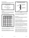
Lubrication
The blower motor and induced draft motor are pre-lubricated
by the manufacturer and do not require further lubricating
attention. However, the motors should be cleaned periodically
to prevent the possibility of overheating due to an accumulation
of dust and dirt on the windings or on the motor exterior.
MAINTENANCE
Failure to follow the safety warnings exactly could result
in dangerous operation, serious injury, death, or property
damage.
Improper servicing could result in dangerous operation,
serious injury, death, or property damage.
• Before servicing, disconnect all electrical power to
furnace.
• When servicing controls, label all wires prior to
disconnecting. Reconnect wires correctly.
• Verify proper operation after servicing.
WARNING
ELECTRICAL SHOCK, FIRE,
OR EXPLOSION HAZARD