


SELF-PRIMING CENTRIFUGAL PUMPS OM--04760
PAGE B -- 1INSTALLATION
INSTALLATION --- SECTION B
Review all SAFETY information in Section A.
Since pump installations are seldom identical, this
section offers only general recommendations and
practices required to inspect, position, and ar-
range the pump and piping.
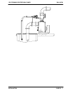
Most of the information pertains to a standard
static lift application where the pump is positioned
above the free level of liquid to be pumped.
If installed in a flooded suction application where
the liquid is supplied to the pump under pressure,
some of the information such as mounting, line
configuration, and priming must be tailored to the
specific application. Since the pressure supplied
to the pump is critical to performance and safety,
be sure tolimitthe incomingpressure to50%ofthe
maximum permissible operating pressure as
shown on the pump performance curve (see Parts
List Manual). If the pump is fitted with a Gorman-
Rupp double grease lubricated seal, the maxi-
mum incoming pressure must be reduced to 10
p.s.i.
For further assistance, contact your Gorman-Rupp
distributor or the Gorman-Rupp Company.
PREINST ALLATION IN SPECTION
The pump assembly was inspected and tested be-
fore shipment from the factory. Before installation,
inspect the pump for damage which may have oc-
curred during shipment. Check as follows:
a. Inspect the pump and power source (if so
equipped) for cracks, dents, damaged
threads, and other obvious damage.
b. Check for and tighten loose attaching hard-
ware. Since gaskets tend to shrink after dry-
ing, check for loose hardware at mating sur-
faces.
c. Carefully read all tags, decals, and markings
on the pump assembly, and perform all duties
indicated. Note that the pump shaft rotates in
the required direction.
d. Check levels and lubricate as necessary. Re-
fer to LUBRICATION in the MAINTENANCE
AND REPAIR section of this manual and any
other literature accompanying the unit and
perform duties as instructed.
e. If the pump and power source have been
stored for more than 12 months, some of the
components or lubricants may have ex-
ceeded their maximum shelf life. These must
be inspected or replaced to ensure maxi-
mum pump service.
If the maximum shelf life has been exceeded, or if
anything appears to be abnormal, contact your
Gorman-Rupp distributor or the factory to deter-
mine the repair or updating policy. Do not put the
pump into service until appropriate action h as
been taken.
Battery Installation
If the pump is engine driven, the engine battery is
not included with the unit unless otherwise speci-
fied on the pump order. See the battery tag in-
cluded with the battery box assembly for battery
specifications. Refer to information accompanying
the battery and/or electrolyte solution for activation
and charging instructions.
Before installing the battery, clean the positive and
negative cable connectors, and the battery termi -
nals. Secure the battery by tightening the hold-
down brackets. The terminals and clamps may be
coated with petroleum jelly to retard corrosion.
Connect and tighten the positive cable first, then
thenegativecable.
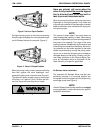
POSITIONING P UMP
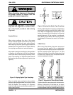
Lifting
Use lifting equipment with a capacity of at least 5
times the weight of the pump, not including the
weight of accessories, wheel kit or optional equip-
ment. Customer installed equipment such as suc-
tion and discharge pipingmust be removed before
attempting to lift.